


Theory of Operation
KEYBOARD
5
5-19
f5-12.wmf
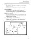
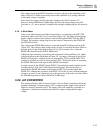
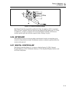
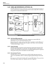
Figure 5-12. Vacuum Fluorescent Display
The Digital Controller sequentially enables the G lines by applying +30V dc (nominal).
When a G line is enabled, electrons flow from the filament to the enabled grid. If a P line
is enabled (i.e., raised to a nominal +30V dc by the Digital Controller), the electrons
continue past the grid and strike the respective plate, causing it to glow.
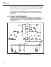
5-26. KEYBOARD
The keyboard consists of a silicone-rubber switch matrix located over metalized epoxy
contacts on the printed wire board. Each button contains a conductive pad that shorts two
contacts when pressed.
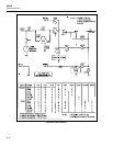
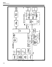
5-27. DIGITAL CONTROLLER
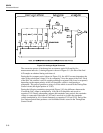
The Digital Controller (Figure 5-13) consists of the In-Guard µC (U202), External
Program Memory (U222), Calibration Memory (U220), Keyboard/Display Interface, and
associated components.