


8842A
Instruction Manual
4-14
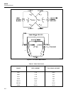
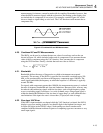
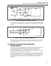
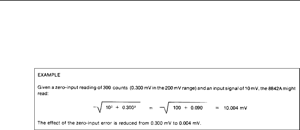
The zero-input error is quickly reduced when the input is increased. The rms converter
error (a dc error) and the internally generated noise (a random ac error) are both
uncorrelated with the input signal. Therefore, when a signal is applied, the resulting
reading is not the simple addition of the signal and the zero-input error, but the square
root of the sum of their squares. This reduces the effect of the error, as shown in the
example in Figure 4-9.
f4-09.wmf
Figure 4-9. Reduction of Zero-Input Error
As long as the 8842A reading is 1,000 counts or more, readings will still be within
specified accuracy.
4-23. MAKING ACCURATE MEASUREMENTS ON THE 20 mV
AND 20
Ω
RANGES
NOTE
When making low-level (uV) measurements after a large step signal has
been applied to the inputs, allow sufficient time for thermal emfs and other
system-related sources of error to settle before taking readings.
The 20 mV dc and 20Ω ranges are the 8842A’s most sensitive ranges. For that reason,
they are also the most susceptible to error from electrical noise, thermal voltages, and (for
resistance measurements) test lead resistance. You can minimize these sources of error by
using good measurement practices.
The most common source of error is electrical noise. Typical sources of noise include
electrostatic noise, inductive pickup noise, radio frequency noise, power line noise and
noise generated by ground loop currents. Noise pickup can be minimized by properly
shielding the test leads between the 8842A and the signal source.
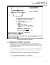
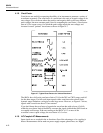
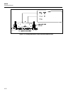
For voltage measurements in most system applications, where common-mode voltages
are typically present, connect the test lead shielding to the 8842A INPUT LO terminal as
shown in Figure 4-10. This configuration minimizes the error caused by current that
would flow in the leads due to common-mode voltages between the measurement and
stimulus points and instrument ground. The 8842A’s INPUT LO terminal is internally
connected to the instrument’s internal guard, which provides a shield between the
instrument’s ground and its sensitive analog circuits. The 8842A’s analog circuits are
isolated from its digital circuits by an electrostatically shielded transformer, whose shield
is also connected to the guard.