


Theory of Operation
DIGITAL CONTROLLER
5
5-23
5-29. Function and Range Control
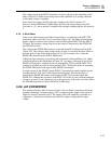
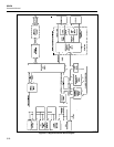
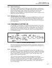
The In-Guard µC configures the DC Scaling circuit, the Track/Hold circuit, and the
Ohms Current Source to provide the proper input switching, scaling, and filtering for
each function, range, and reading rate. It does this by controlling dedicated output lines
which control relays and FET switches, and by sending configuration codes out on the
bus. The quad analog switches (U301, U302, U303, U402, and U403) latch the
configuration codes and perform any level-shifting needed to control their internal
MOSFET switches. Some of the switches require dynamic timing signals from the
custom A/D IC (U101); these signals are combined appropriately in the quad analog
switches with the configuration codes.
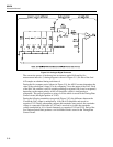
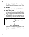
5-30. A/D Control and Computation
The In-Guard µC initiates each A/D sample by pulling line TR low. When the µC is
reset, it senses the power line frequency on line FREQ REF. The µC then sets its internal
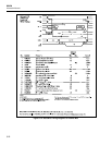
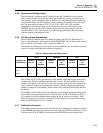
timer so that the A/D sample rate is as shown in Table 5-1.
The number of readings per second for the slow and medium rates are chosen to provide
rejection of input signals that are at the line frequencies.
Table 5-1. Sample Rates and Reading Rates
SLOW MEDIUM FAST
POWER LINE
FREQUENCY
Samples
per Sec
Samples
per
Reading
Samples
per Sec
Samples
per
Reading
Samples
per Sec
Samples
per
Reading
50 Hz 66.67 32 66.67 4 100 1
60 Hz 80 32 80 4 100 1
400 Hz 76.19 32 76.19 4 100 1
The custom A/D IC (U101) generates five 6-bit numbers after each trigger from the µC
and then pulls INT low, telling the µC that data is ready. The µC reads the five 6-bit
numbers over the bus (CS7 pulses low five times for five read cycles) and computes the
value of the A/D sample using calibration constants. The µC averages the appropriate
number of samples for one reading, which is then sent to the keyboard/display interface
for display.
For example, with a 60-Hz power-line frequency, an externally triggered reading in the
slow reading rate would cause the µC to send 32 pulses on TR at an 80 Hz rate. The 32
A/D samples would be calibrated and averaged by the µC and sent for display. With
internal triggering, the A/D runs continuously at 80 samples per second with a reading
being sent to the display every 32 samples.
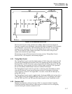
5-31. Calibration Correction
The calibration constants used by the In-Guard µC in computing each reading are stored
in the EEROM (electronically erasable read-only memory) Calibration Memory (U220).
The front panel CAL ENABLE switch protects the EEROM from accidental writes.