


Theory of Operation
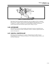
A/D CONVERTER
5
5-15
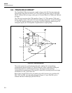
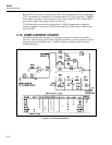
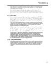
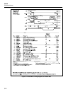
The voltage sensed at the INPUT terminals is scaled as shown by the simplified switch
table in Figure 5-8. (Refer to the track period of the track/hold cycle, during which the
scaled input voltage is sampled.)
In the lower five ranges, the full scale input voltage to the A/D Converter is 2V.
However, in the 2000 kΩ and 20 MΩ ranges, the full-scale input voltage to the A/D
Converter is +1V; the in-guard uC completes the scaling by multiplying the A/D result by
2.
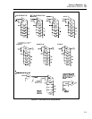
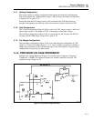
5-19. 4-Wire Ohms
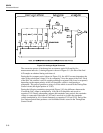
In the 4-wire ohms function, the Ohms Current Source is connected to the INPUT HI
terminal by ohms relay K401 as in 2-wire ohms (Figure 5-8). The Ohms Current Source
applies a known current to the resistance under test through the INPUT HI and INPUT
LO leads. The resulting voltage drop across the resistor is measured by the SENSE HI
and SENSE LO leads.
The voltage at the SENSE HI terminal is connected to the DC Scaling circuit by Q303
(Figure 5-8). The voltage is then scaled exactly as in the 2-wire ohms function. (Refer to
the track period in the switch table in Figure 5-8.) Q310 is turned off to isolate the
SENSE HI terminal from the INPUT HI terminal.
Additional input switching occurs during the hold period of the track/hold cycle. (Refer
to the hold period in the switch table in Figure 5-8.) In ranges r1 through r4, and r8, the
SENSE LO terminal is switched into the dc input path by U301D, and the INPUT LO
terminal is switched out of the dc input path by U301C. This has the effect of measuring
the SENSE HI terminal with respect to the SENSE LO terminal.
In ranges r5 and r6, the SENSE LO and INPUT LO terminals are both switched into the
dc input path by U301C and U301D during the hold period. This has the effect of
measuring the SENSE HI terminal with respect to INPUT LO terminal rather than
SENSE LO. Although the resistance of the INPUT LO lead is in series with the unknown
resistance, accuracy is not affected as long as the resistance of the lead is less than 10Ω in
the 2000 kΩ range and less than 100Ω in the 20 MΩ range.
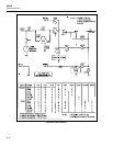
5-20. A/D CONVERTER
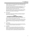
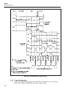
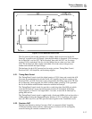
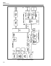
The Analog-to-Digital (A/D) Converter (Figure 5-9) uses Fluke’s patented recirculating
remainder technique. An input voltage (Vin) is compared to the output of the precision
Digital-to-Analog Converter (DAC). The output of the A/D Amplifier, connected as a
comparator, is monitored to indicate when the DAC output is larger than the input
voltage.