


Maintenance
TROUBLESHOOTING
6
6-41
A failure in the instrument may cause the 8842A to display random patterns or nothing at
all. Usually, analog circuit failures do not cause the display to go blank or display random
patterns. The best place to start troubleshooting a "dead" instrument or an instrument with
a non-functional display is to check the power supply with a voltmeter for proper levels
and to use an oscilloscope to check the supplies for oscillations. If all of the supplies are
working correctly, check the clock for the In-Guard µC at U202-2. The signal should be
an 8 MHz sine wave approximately 3.5V peak-to-peak. Then check the 1 MHz output of
the A/D IC (U101) at U212-3. (If not present, check at the A/D IC at U101-14.) The
signal should be a 1 MHz square wave approximately 5V peak-to-peak. The 8 MHz sine
wave is generated by the clock circuit of the In-Guard µC, and the 1 MHz signal is the 8
MHz signal divided by a counter in the A/D IC. If the clock signals are correct, proceed
to the heading Digital Controller Troubleshooting, below, for detailed troubleshooting
instructions.
If a problem occurs in the keyboard/display area, the instrument may appear to be totally
inoperative even when the measurement circuitry is still functional. The heading Digital
Controller Troubleshooting provides detailed instructions on locating problems in the
display/keyboard system.
Finally, as in most processor-based systems, there are communication links between the
various parts of the system. Specifically, in the 8842A, there is a bus interface between
analog and digital control circuits and a guard-crossing interface between logic circuits
which may be separated by large potentials. Failures in these links can generate problems
that may be difficult to locate and repair. However, such failures will in turn cause
failures in some analog and or digital section. Thus, indirectly, troubleshooting the
affected section will lead to correction of problems in the internal bus or guard-crossing
circuit.
6-38. Diagnostic Self-Tests
To run the diagnostic self-tests, disconnect the test leads and press the SRQ button for 3
seconds. If the test leads are left attached to the input terminals the 8842A may indicate
errors are present (most likely, errors 5, 7, 8, 9, and 10). Also, if the FRONT/REAR
switch is in the REAR position, the 8842A skips tests 3 and 4, and if Option -09 is not
installed, the 8842A skips tests 1, 2, and 3. For all tests, there is a 0.5 second delay period
before any readings are taken. The tests are all contingent on the A/D Converter being
properly calibrated, but do not depend on the Offset and Gain Calibration constants.
Failing the tests indicates that key portions of the 8842A are not performing properly.
Passing the tests gives approximately a 90% probability that all VDC ranges and range r6
of 2-wire ohms can be calibrated. Passing the tests also gives a reasonable probability
that it will give accurate measurements in VDC and range r6 of 2-wire ohms. However,
passing the tests does not guarantee that the instrument can be calibrated in VAC, mA
DC, mA AC, 4-wire ohms, or ranges r1 to r5 of 2-wire ohms.
NOTE
If the A/D Converter or Precision Voltage Reference is not working, all
analog tests would show an error. If the A/D Converter is not calibrated,
tests 7, 15, 19 could show an error.
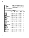
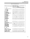
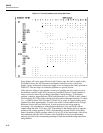
If the analog self-tests indicate an error, it may be possible to isolate the problem as
follows:
1. While the error code is being displayed, press the SRQ button. This latches the
8842A into the particular test configuration.
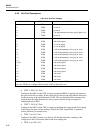
2. Referring to Table 6-18, check that the test point voltages are as shown using another
DMM.