


Theory of Operation
INTRODUCTION
5
5-3
5-1. INTRODUCTION
This section presents an overall functional description of the 8842A, followed by a
detailed circuit description. The descriptions are supported by simplified schematics in
text and by the complete schematics in Section 10.
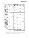
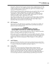
5-2. OVERALL FUNCTIONAL DESCRIPTION
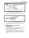
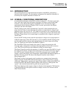
A functional block diagram of the 8842A is shown in Figure 5-1. The basic signal path
flows from left to right across the center of the page. The input is sensed at the input
terminals, scaled, directed through the Track/Hold circuit, converted into digital
representation by the Analog-to-Digital (A/D) Converter, processed by the Digital
Controller, and sent to the display.
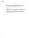
The DC Scaling circuit, which constitutes the "front end" of the instrument, has two
major functions. First, it senses the input and produces an equivalent dc voltage for all
functions except VAC and mA AC. (AC inputs are converted to a dc voltage by the True
RMS AC Option.) Resistances are sensed as a dc voltage using a known test current from
the Ohms Current Source. A dc current input is converted to a dc voltage by a precision
current shunt.
Second, the DC Scaling circuit scales the equivalent dc voltages (for in-range inputs) to
within the input range of the A/D Converter (+/-2V). In addition, the DC Scaling circuit
provides input protection and provides analog filtering for certain ranges and reading
rates. (AC inputs are scaled by the True RMS AC Option.)
The Track/Hold (T/H) circuit samples the scaled dc voltage and presents the A/D
Converter with a voltage that is constant for the input portion of each A/D conversion
cycle. The T/H circuit also provides additional scaling for certain ranges.
The Digital Controller controls the operation of virtually every part of the 8842A. It reads
the front panel keyboard, configures the instrument for each function and range, triggers
the A/D Converter, calculates the result of each A/D conversion cycle, averages A/D
samples, controls the display, and communicates with the IEEE-488 Interface Option via
the Guard Crossing circuit. The heart of the Digital Controller is the In-Guard
Microcomputer (µC).
The Guard Crossing circuit permits serial asynchronous communication between the
Digital Controller and the IEEE-488 Interface Option, while isolating the two circuits
electrically. Whereas the in-guard power supply floats with the voltage at the INPUT LO
terminal, the IEEE-488 Interface Option operates with reference to earth ground. The
"guard" is the isolation between the in-guard and out-guard circuits.
The Power Supply provides supply voltages to all parts of the instrument. The Precision
Voltage Reference provides precise reference voltages for the A/D Converter and the
Ohms Current Source.