


8842A
Instruction Manual
3-28
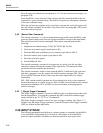
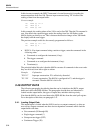
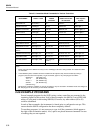
BIT: 8 7 6 5 4 3 2 1
0 RQS ANY
ERROR
DATA
AVAILIBLE
CAL STEP
COMPLETE
FRONT
PANEL SRQ
0 OVER-
RANGE
DECIMAL
VALUE:
64 32 16 8 4 2 1
Bit Name Set Cleared
1 Overrange An overrange condition occurs Device command received, or
Bus or Rear Panel Trigger, or
Output buffer is read
2 Not used Never Always
3 Front panel SRQ Front panel SRQ button
pressed
Device command received
4 Cal Step Complete Completion of store command
(C0)
Device command received
5 Data Availible Output buffer loaded with any
data (Readings, Error
Messages. Get Responses)
Device command received, or
Bus or Rear Panel Trigger, or
Output buffer is read
6 Any Error An error condition occurs. At
the same time the output buffer
is loaded with an error
message. This sets bit 5.
Device command received, or
Output buffer is read
7 RQS Any SRQ mask-enabled bit is
set.
All SRQ mask-enabled bits are
cleared
8 Not used Never Always
Figure 3-8. Serial Poll Register
For example, the serial poll register reads 00010000 (binary) when data is available. This
value is read in binary by the controller, which might numerically reformat the value to
16 (decimal) or 10 (hexadecimal).
The serial poll register is cleared whenever the 8842A receives a new input command
string.
3-51. The SRQ Mask
The SRQ mask is a two-digit integer that specifies which conditions will generate a
service request. The SRQ mask is entered using the P1 command and can be read with
the G1 command. The conditions corresponding to each SRQ mask value are listed under
G1 in Table 3-1.