


8842A
Instruction Manual
3-6
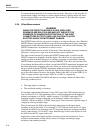
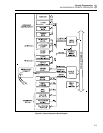
Information is transferred between blocks by device-dependent commands. Each
command is shown next to an arrowhead which indicates the resulting information
transfer. For example, Put command P0 takes a number from the input buffer and stores it
in the primary status registers. Likewise, Get command G0 gets the content of the
primary status registers and copies it into the output buffer.
3-5. A NOTE ABOUT EXAMPLES
In the examples in this manual, device-dependent commands are shown enclosed within
quotation marks, as they would be entered in Fluke BASIC. For clarity, the commands
are also separated by spaces. However, the spaces are are not necessary and may be
omitted.
Example Explanation
"* F3 R1 S1 T2" This example is equivalent to "*F3R1S1T2" or
"*,F3,R1,S1,T2".
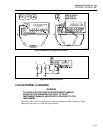
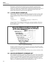
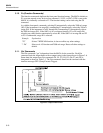
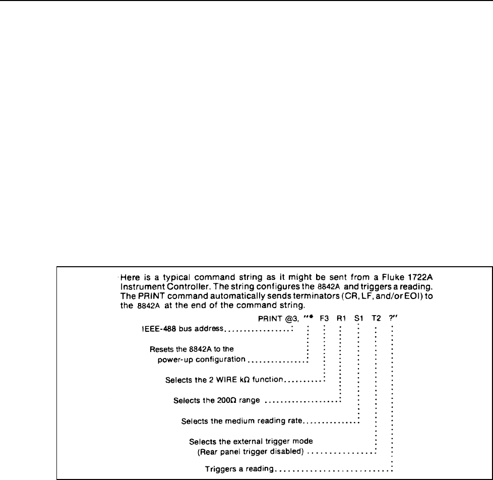
Using the Fluke 1722A Instrument Controller, these commands might be written into a
BASIC program as shown in Figure 3-3. Examples using other controllers are given at
the end of this section.
f3-03.wmf
Figure 3-3. Typical Command String
Examples of 8842A output data show the terminators CR and LF. The terminator EOI is
not shown because it is a uniline message. However, the terminators CR, LF, and EOI are
all selectable using the Write commands.
For reference, the ASCII and IEEE Std 488-1978 bus codes are shown at the back of this
section.
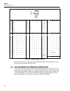
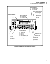
3-6. DEVICE-DEPENDENT COMMAND SET
Device-dependent commands are the heart of 8842A remote control. They tell the 8842A
how and when to make measurements, when to put data on the bus, when to make service
requests, etc. Commands which correspond directly to the front panel controls or display
are shown in Figure 3-4. The complete set of device-dependent commands is listed in
Figure 3-5. The commands may be entered using either upper- or lower-case letters. See
Table 6-15 for conditions under which certain commands are not valid.