


Maintenance
REASSEMBLY PROCEDURE
6
6-35
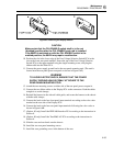
f6-08.wmf
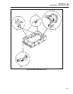
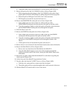
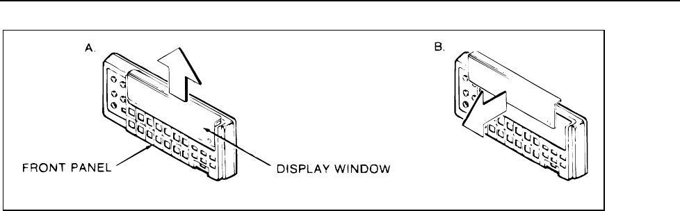
Figure 6-8. Removing the Display Window
CAUTION
Make certain that the CAL ENABLE switch shaft is in the out
(disabled) position after the CAL ENABLE push rod is installed.
If the 8842A is switched on with the CAL ENABLE switch in the
enabled position, the 8842A may require recalibration.
10. Position the slot in the lower edge of the Line Voltage Selection Switch PCA in the
slot on the lower rear panel standoff. Secure the top of the Line Voltage Selection
Switch PCA to the upper standoff using the single mounting screw, and plug the
ribbon cable into the Main PCA.
11. Connect the power supply ground lead to the rear panel mounting stud. (The stud is
located near the rear panel power receptacle as shown in Figure 6-6F.)
WARNING
TO AVOID ELECTRIC SHOCK, ENSURE THAT THE POWER
SUPPLY GROUND LEAD IS FIRMLY ATTACHED TO THE
REAR PANEL MOUNTING STUD.
12. Attach the two mounting screws on either side of the rear panel power receptacle.
13. Connect the two ribbon cables to the Display PCA to the connectors. Push the cables
straight in to avoid damage.
14. Reinstall the harness in the sidewall cable guide, and secure the harness to the chassis
with the cable clamps.
15. Connect the leads to the four front panel input terminals according to the color codes
marked on the rear side of the Display PCA.
16. Connect the leads to the four rear panel input terminals following the color codes as
shown in Figure 6-6B.
17. (Option -05 only) Install the IEEE-488 Interface PCA according to the instructions in
Section 8.
18. (Option -09 only) Install the True RMS AC PCA according to the instructions in
Section 8.
19. Slide the case and rear bezel onto the chassis.
20. Install the two rear panel mounting screws.
21. Install the case grounding screw in the bottom of the case.