


Maintenance
TROUBLESHOOTING
6
6-65
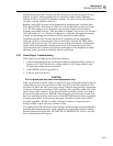
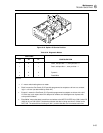
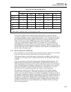
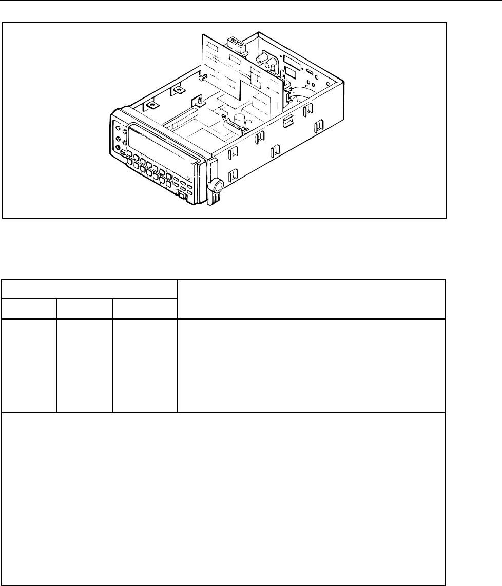
f6-19.wmf
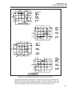
Figure 6-19. Option -05 Service Position
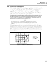
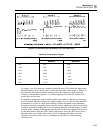
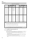
Table 6-24. Diagnostic Modes
SWITCHES
A3 A2 A1
CONFIGURATION
1 0 1 Static, odd-port bits = 1, even-port bits = 0
1 1 1 Static, odd-port bits = , even-port bits = 1
1 X 0 Dynamic
0 X x Read/Write
NOTES:
• “x” means switch setting does not matter.
• “Static” means the Out-Guard µC I/O port bits programmed as outputs are driven to a constant
logic 1 or 0 level (as determined by switch A2).
• “Dynamic” means the Out-Guard µC I/O port bits programmed as outputs are driven with a 610
Hz, 50% duty cycle square wave. All odd port bit numbers are 180 degrees out of phase with
even port bit numbers.
• “Read/Write” means that data is read from and written to the NEC7210 IEEE chip (U901) when DS
(U901-8) is low. R/W (U901-7) determines whether the data is being read from or written to the
NEC7120. The address bits are always 3 (0011) and the data bits are incremented each time.