


Maintenance
TROUBLESHOOTING
6
6-55
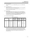
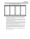
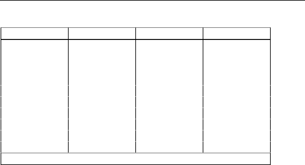
Table 6-22. DC Scaling and Track/Hold Supply Voltages
PIN OR DEVICE SUPPLY VOLTAGE PIN OR DEVICE SUPPLY VOLTAGE
U301-6 +5V U303-20 +7.5V
U301-10 0V U303-11 -8.2V
U301-20 +7.5V U304-4 -8.2V
U301-11 -5V U304-7 +7.5V
U302-6 +5V U305-3 +5V
U302-10 0V U305-12 -5.5V(Nom)*
U302-20 +7.5V U307-4 -15V
U302-11 -5V U307-7 +15V
U303-6 +5V Q305,c +30V
U303-10 0V Q306,c -30V
*With 0V input.
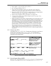
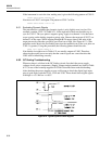
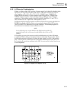
In the 20V range, any voltage applied to the HI INPUT terminal (relative to Reference
Low) should be present at U306-3. If it isn’t, trace the voltage from the HI INPUT
terminal to U306-3 to isolate the problem.
To check U306, select the VDC function and the 2V range. Measure the voltage at TP302
while applying first 1V and then 0V (a short) across the HI and LO INPUT terminals. If
1V and then 0V appear at TP302, U306 is probably OK. If not, the problem is in U306 or
its bootstrap supplies (TP301 and TP303).
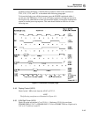
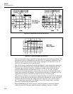
To check the bootstrap supplies, put the 8842A in the 20V range and measure the voltage
at TP301, TP302, and TP303. TP301 should be 6.3V (nominal) above TP302, and TP303
should be 6.2V (nominal) below TP302. If the bootstrap supplies are operating correctly,
measure the voltage at U306-3 and U306-6 for input voltages of +20V and -20V; if the
voltage at U306-3 differs from U306-6, then U306 is bad.
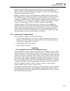
To check the dc input path after U306, short the HI and LO INPUT terminals and read
the display. If zero is displayed for ranges r3 and r5 but not for r1, r2, and r4, then the
signal path including Q311 and U301B is suspect. To check Q311, apply a 1V dc input in
the 2V range and check that the voltage at the drain and source of Q311 is 1V. If not,
Q311 or its driver is bad. If 1V appears at U301-16, but not at the display, then U301
may be bad.
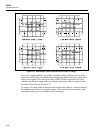
If zero is not displayed for r3 and r5 with the HI and LO INPUT terminals shorted, then
Z301 or U302D is probably bad.