


Theory of Operation
DC SCALING
5
5-7
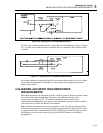
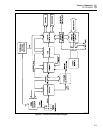
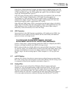
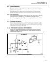
In the 20 mV, 200 mV and and 2V ranges, the input voltage is applied directly to the T/H
Amplifier via Q310, Q311, and U301B. In the 20 mV range, the T/H Amplifier has a gain
of 100; in the 200 mV range, the T/H Amplifier has a gain of 10; in all other dc voltage
ranges, the T/H Amplifier has a gain of 1.
In the 20V range, the input voltage is buffered by unity-gain amplifier U306, and divided
by 10 by Z301. To allow U306 to handle +/-20V inputs, its power supplies are
"bootstrapped" by Q305 and Q306, so that the output voltage of U306 determines the
midpoint of its supply voltages. The positive supply is approximately 6.2V above the
input and the negative supply is approximately 6.2V below.
In the 200V and 1000V ranges, K301 is de-energized and the input voltage is divided by
100 by Z302. In the 200V range, the reduced input voltage is then applied directly to the
T/H Amplifier as in the 2V range. In the 1000V range, the reduced input voltage is
buffered by U306 and divided by 10 as in the 20V range.
5-6. VDC Protection
Input protection for the VDC function is provided by a 1K, fusible resistor (R309), four
metal-oxide varistors (MOVs) (RV301, RV402, RV403, and RV404), and additional
protection resistors and clamp circuits.
WARNING
TO AVOID INJURY OR EQUIPMENT DAMAGE, USE EXACT
REPLACEMENT PARTS FOR ALL PROTECTION COMPONENTS.
In all dc voltage ranges, voltage transients greater than 1560V are clamped by the MOVs.
Extreme overvoltage conditions cause R309 to fail open-circuit.
R309 is followed either by a 99 kΩ, 10W resistor network (Z304) in the 20 mV, 200 mV,
2V, and 20V ranges, or by 10 MΩ (Z302) to ground in the 200V and 1000V ranges. Z304
provides current limiting in extreme overvoltage conditions in the 20 mV, 200 mV, 2V,
and 20V ranges. The non-inverting input of U306 is clamped to +/-25V by Q307 and
Q308.
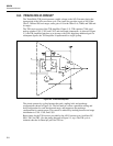
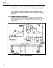
5-7. mA DC Scaling
In the mA DC function, the unknown current causes a voltage drop across current shunt
R319. This voltage drop is then measured as in the VDC function. The DC Scaling circuit
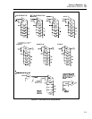
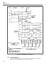
is configured as shown by the simplified switch table in Figure 5-2.
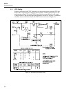
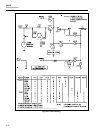
5-8. Analog Filter
The three-pole, low-pass analog filter (U304) has a Bessel response with corner
frequency at 7 Hz, giving approximately 50 dB of rejection at 50 Hz. The filter is used
for the slow reading rate and is used in the VDC ranges and lowest three ohms ranges.
The filter is also used in the 20mV DC, 20Ω, and 200 mA DC ranges when in the
medium reading rate. The filter is switched into the input signal path by Q304 (Figure 5-
2). In some ranges and functions, additional filtering is provided by Q317 and C314.