


8842A
Instruction Manual
5-18
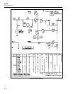
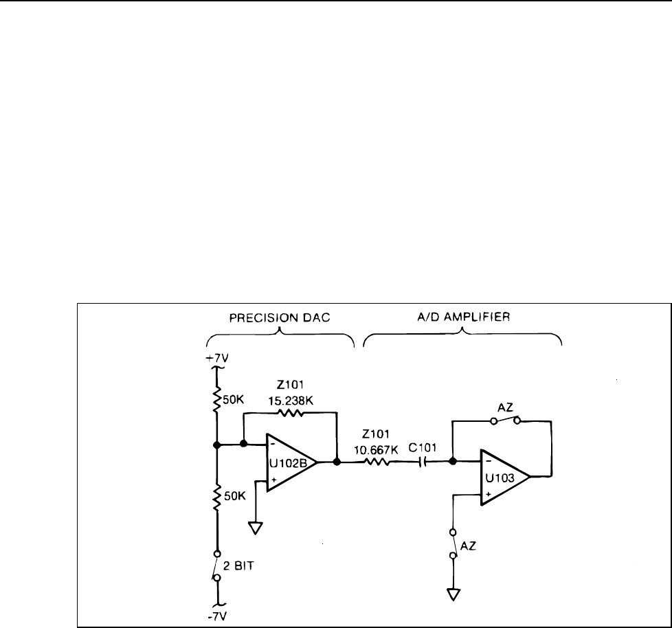
The bit-switches determine the output voltage of U102B by controlling the binary ladder
network. The gain of U102B is set by the ratio of a precision feedback resistor (Z101-7, -
8) and the equivalent output resistance of the ladder network.
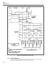
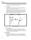
5-23. A/D Amplifier
The A/D Amplifier is composed of a comparator/amplifier (U103), two remainder-
storage capacitors (C103 and C102), an autozero storage capacitor (C101), and several
digitally controlled analog switches contained in U101.
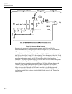
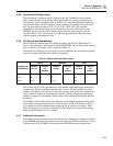
The A/D Amplifier has three modes of operation: autozero mode, where any offsets in
the A/D input are stored on C101 so as to be cancelled later; compare mode, where the
A/D input is compared to the DAC output; and remainder-store mode, where U103
amplifies and stores the difference between the A/D input and the DAC output on one of
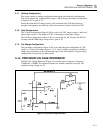
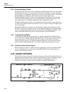
the two remainder-storage capacitors (C102 or C103). The autozero mode is shown in
Figure 5-11. The other modes are shown in Figures 5-9 and 5-10.
f5-11.wmf
Figure 5-11. Autozero Period
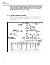
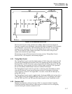
5-24. Bootstrap Supplies
The bootstrap supplies are composed of U102A, Q101, Q102, CR103, CR104, and
associated components. The bootstrap supplies enhance the gain accuracy of U103.
During compare periods, the bootstrap supplies limit the output of U103 to minimize the
time it takes to recover from being driven to a supply rail. Both functions are achieved by
manipulating the supplies of U103 (BS1 and BS2).
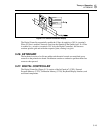
5-25. DISPLAY
The vacuum fluorescent display is similar to a vacuum tube, containing eight control
grids and 69 phosphor-coated plates which form the display segments and annunciators.
(See Figure 5-12.) The filament voltage is 4.5V ac, with a +5V dc bias. Each plate is
controlled by a G line and a P line. The G lines go to the control grids, and the P lines go
to the plates.