Maintenance
TROUBLESHOOTING
6
6-63
f6-18.wmf
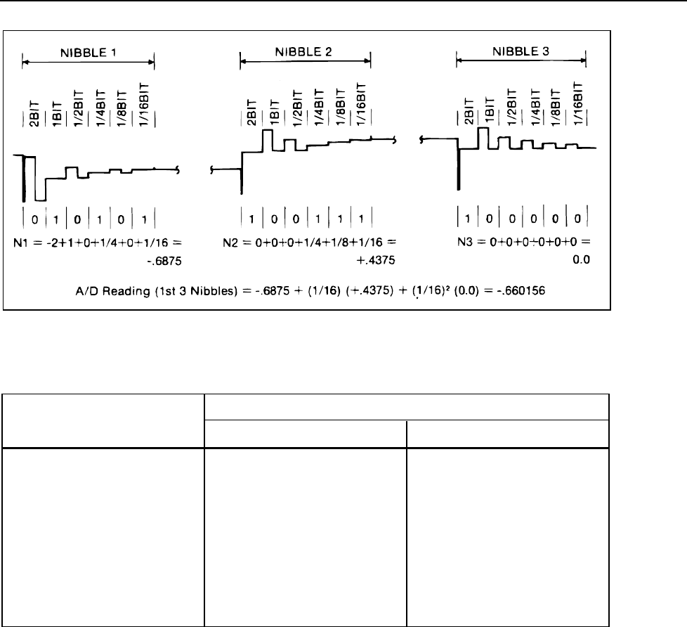
Figure 6-18. Calculating the A/D Reading From TP102 Waveform
Table 6-23. Power Supply Voltages
LIMITS (in volts)TEST POINT
MINIMUM MAXIMUM
+5V 4.75 5.25
+7.5V 7.00 7.87
+15V 14.25 15.75
+30V 28.45 31.55
-8.2 -8.61 -7.60
-15V -15.75 -14.25
-30V -31.55 -28.45
If a supply is too low, there are a number of possible causes. First check the input to the
affected regulator. If it is not at least 1V above the maximum output given in Table 6-23,
the cause may be a bad transformer winding (check the resistance), open or shorted
rectifiers, a shorted filter capacitor, or a shorted regulator. The latter two failures will
usually blow the line fuse.
All regulators incorporate current-limiting which allows them to shut down in the event
of a load failure. Therefore if the power supply output is too low, the first step should be
to determine if it is due to a high load caused by a failure elsewhere in the instrument.
Frequently the faulty component can be found by using a multimeter with at least 5 digits
resolution to check the supply pins of all components powered from that supply. Connect
one lead of the voltmeter to the appropriate test point for the power supply under test and
use the other lead to probe the loads. Small voltage drops across the PCA traces can be
detected in this way, and the fault isolated. If any component other than one of the
regulators is too hot to touch, there is something wrong with it or with something
connected to it.


