


8842A
Instruction Manual
6-60
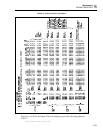
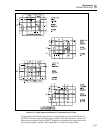
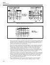
f6-15.wmf
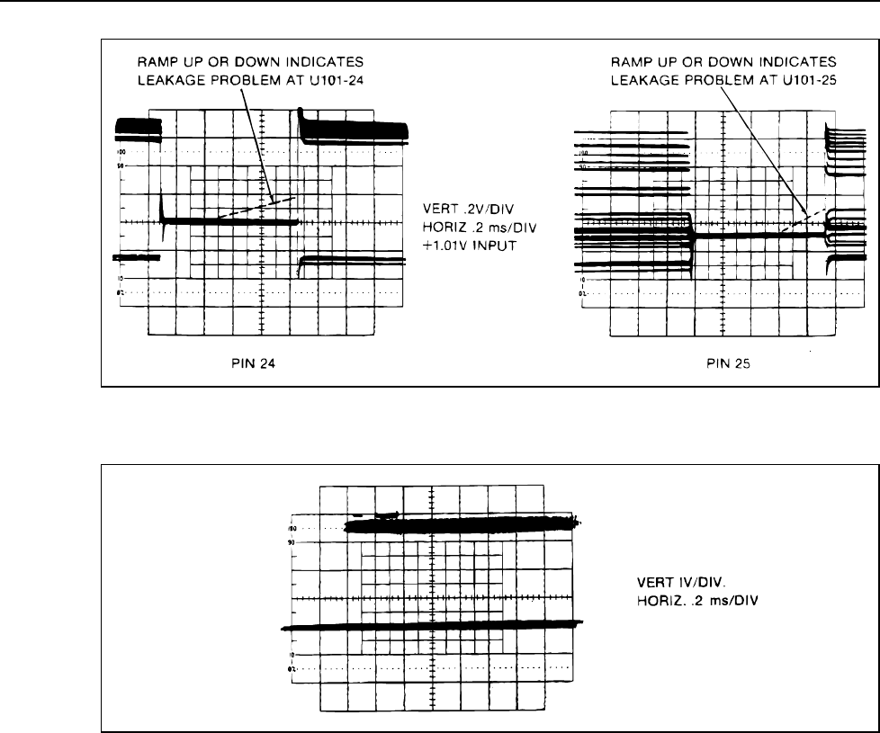
Figure 6-15. Waveforms at U101-24 and U101-25
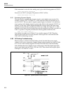
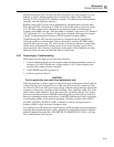
f6-16.wmf
Figure 6-16. Typical Bus Data Line Waveform
The waveform at the storage capacitors can often be used to locate leakage problems. The
leakage can be due to contamination on the Main PCA or to defective switches in U101.
Figure 6-15 shows the waveforms across storage capacitors C102 and C103 (U101-24
and U101-25, respectively) for a specific input.
The A/D Converter communicates with the In-Guard µC via the internal bus, which also
goes to several other sections of the instrument. What looks like a problem in the A/D
Converter may actually be caused by a problem in another section of the instrument
which is loading down the bus data lines (U101-1, -2, -3, -38, -39, -40). A typical
waveform at one of the data lines is shown in Figure 6-16. One of the data lines can be
loaded down so that the In-Guard µC fails to recognize data sent over that line. If so, the
amplitude of the signal of the bad line would be less than 3V peak-to-peak.
One technique of finding an overloaded or shorted data line is to remove the In-Guard µC
and drive one data line at a time through a 1 kΩ resistor. Measure the voltage drop across
a length of the line. Normally the voltage drop across the line is zero volts (less than 5
µV). Voltage drops larger than 5 µV indicate a short. (The voltage drop is caused by
excessive current flowing through the line.)
When troubleshooting the A/D Converter it may be desirable to determine what the
reading is at the A/D Converter when the display is definitely incorrect. A digital