


8842A
Instruction Manual
6-66
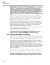
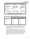
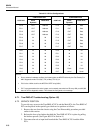
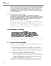
Table 6-25. I/O Port Configurations
CONFIGURATION CONFIGURATION
PORT BIT
Static
Dynamic
Read/Write
PORT BIT
Static
Dynamic
Read/Write
PO-0 OUT Address P1-0 OUT Data
PO-1 OUT Address P1-1 OUT Data
PO-2 OUT Address P1-2 OUT Data
PO-3 OUT Address P1-3 OUT Data
PO-4 IN IN P1-4 OUT Data
PO-5 IN IN P1-5 OUT Data
PO-6 IN IN P1-6 OUT Data
PO-7 IN IN P1-7 OUT Data
P2-0 IN IN P3-0 IN IN
P2-1 IN IN P3-1 IN IN
P2-2 IN IN P3-2 IN IN
P2-3 IN IN P3-3 IN IN
P2-4 IN IN P3-4 IN IN
P2-5 IN IN P3-5 IN IN
P2-6 IN IN P3-6 Clock Clock
P2-7 IN IN P3-7 serial Serial
NOTES:
• Due to external hardware conflicts, the following bits are NEVER driven by the Out-Guard µC in
ANY diagnostic mode: P0-4,5,6,7; P2 (all bits); P3-1,2,3,4.
• P3-6 is the 4 MHz clock for the NEC7210 IEEE chip (U901).
• P3-7 is programmed as the serial output, and constantly transmits hex 55 every 820 µs at 62,000
baud in all four diagnostic modes. This causes the front panel error message.
6-71. True RMS AC Troubleshooting (Option -09)
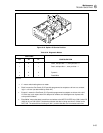
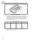
6-72. SERVICE POSITION
To provide easy access to the True RMS AC PCA and the Main PCA, the True RMS AC
PCA can be placed in the specially provided service position as follows:
1. Remove the case from the chassis using the Case Disassembly procedure provided
earlier in this section.
2. Release the four nylon latches that hold the True RMS AC PCA in place by pulling
the latches upward. (See Figure 809-1E in Section 8.)
3. Disconnect the red ac input lead from both the True RMS AC PCA and the Main
PCA.