8842A
Instruction Manual
3-16
"N3120 P0" Identical to F3 R1 S2 T0. Selects 2 WIRE kΩ function, 200Ω range,
fast sample rate, continuous trigger.
The P0 command allows broadside loading of the Function, Range, Reading Rate, and
Trigger Mode commands (F, R, S, and T). The codes for these commands are listed in
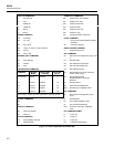
Figure 3-5.
A numeric entry for P0 must be within +1000 and +6824. Each of the four digits must not
exceed its maximum allowed value (6, 8, 2, and 4, respectively) or an error message will
occur and the instrument configuration will remain unchanged. The entry may be
expressed as an integer, real number, or real number with exponent, as described under
the N command. Any fractional part is ignored.
Example Explanation
"N3112 P0" Sets the 8842A to F3, R1, S1, and T2.
3-24. P1 (Put SRQ Mask)
Format Explanation
N<SRQ mask>P1 Where <SRQ mask> is a two-digit integer from 00 to 63.
The P1 command is used to program the 8842A to make service requests on user-
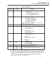
specified conditions. The two-digit code for the SRQ mask is interpreted in Table 3-1
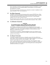
under the G1 command. For more about the SRQ mask, see paragraph 3-51.
Numeric entries for the P1 command must be between 0 and +63 (inclusive), or an error
will occur and the SRQ mask will remain unchanged. The entry may be expressed as an
integer, real number, or real number with exponent, as described under the N command.
Any fractional part is ignored.
Example Explanation
"N0.17E+2 P1" Sets SRQ mask to 17. Enables SRQ on data available or overrange.
"N1 P1" Sets SRQ mask to 01. (A leading zero is assumed.) Enables SRQ on
overrange.
3-25. P2 (Put Calibration Value)
Format Explanation
N<value>P2 Where <value> can be an integer, real number, or real number with
exponent, as described under the N command.
Example Explanation
"N1 P2" If the 8842A is in VDC, the next calibration input expected is
1.00000V dc.
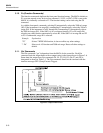
The P2 command is used to enter variable input calibration values just like the front panel
VAR IN button. To accept the P2 command, the 8842A must be in the calibration mode
(enabled by pressing the front panel CAL ENABLE switch). Otherwise, the P2 command
will generate an error message.
The variable input is a measurement value that is to be used as the calibration value for
the next calibration step. Its format is the same as a measurement value. But since it is
coming from the controller, the value can be specified using any valid format (signed
interger, real number, or real number with exponent). For example, if the 8842A prompts
for an input value of 100Ω for the next calibration step, but the available source is
98.97Ω, the variable input can be specified as "N+9.897E+1", "N0.9897E2", N9897E-2",


