


Option –09 True RMS AC
INTRODUCTION
809-3
809-1. INTRODUCTION
The True RMS AC option gives the 8842A the ability to make ac voltage and current
measurements. The ac functions are selected with the front panel VAC and mA AC
buttons, or by remote commands if the IEEE-488 Interface option is installed.
Specifications for Option -09 are shown in Section 1, Table 1-1.
809-2. INSTALLATION
The True RMS AC option is contained on a single, easy-to-install printed circuited
assembly (PCA). To install the option, proceed as follows:
WARNING
TO AVOID ELECTRIC SHOCK, DISCONNECT THE POWER
CORD AND TEST LEADS BEFORE REMOVING THE
INSTRUMENT CASE.
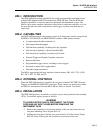
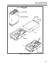
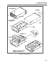
1. Remove the grounding screw from the bottom of the case and remove the two rear
panel mounting screws (Figure 809-1A).
2. Holding the front panel, slide the case and rear bezel off of the chassis (Figure
809-1B). (At this point, the rear bezel is not secured to the case.)
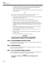
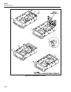
3. Holding the True RMS AC PCA slightly above the chassis, component side down,
connect the the ribbon cable from the True RMS AC PCA to the Main PCA and
latch it in place. (See Figure 809-1C and D.)
4. Connect the red lead from the True RMS AC PCA to stud W301 on the Main
PCA. (See Figure 809-1C.) The stud is located next to the forward end of the
FRONT/REAR switch.
5. Make sure the heads of the four plastic latches are in the extended position. Guide
the PCA into the 4 circuit board supports.
6. Fasten the True RMS AC PCA to the chassis by pressing the four nylon latches
into the mounting supports on the chassis. (See Figure 809-1E.)
7. Reinstall the cover and rear bezel on the chassis and attach the two rear panel
mounting screws.
8. Attach the grounding screw to the bottom of the case.
WARNING
TO AVOID ELECTRIC SHOCK, ENSURE THE GROUNDING
SCREW IS FIRMLY ATTACHED TO THE CASE BOTTOM.
9. Calibrate the VAC voltage and mA AC functions according to the calibration
instructions given in the Maintenance section.