


8842A
Instruction Manual
3-4
A
D
D
R
E
S
S
T
A
L
K
O
N
L
Y
A5 A4 A3 A2 A1 A
D
D
R
E
S
S
T
A
L
K
O
N
L
Y
A5 A4 A3 A2 A1 A
D
D
R
E
S
S
T
A
L
K
O
N
L
Y
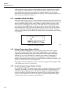
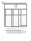
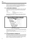
A5 A4 A3 A2 A1
00 0 0 0000 11 001011 22 0 10110
01 0 0 0001 12 001100 23 0 10111
02 0 0 0010 13 001101 24 0 11000
03 0 0 0011 14 001110 25 0 11001
04 0 0 0100 15 001111 26 0 11010
05 0 0 0101 16 010000 27 0 11011
06 0 0 0110 17 010001 28 0 11100
07 0 0 0111 18 010010 29 0 11101
08 0 0 1000 19 010011 30 0 11110
09 0 0 1001 20 010100 31 Not allowed
10 0 0 1010 21 010101 1 XXXXXTALK
ONLY
X = setting does not matter
f3-01.wmf
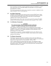
Figure 3-1. IEEE-488 Address Selection
Whenever the 8842A is in the local state, the IEEE-488 address can be displayed on the
front panel by pressing the LOCAL button.
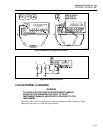
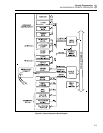
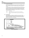
3-4. AN OVERVIEW OF REMOTE OPERATION
An overview of remote operation is presented in the block diagram in Figure 3-2. Each
block represents a register, buffer, etc., contained in the 8842A. The status registers in the
center column indicate the instrument’s status, including its function, range, reading rate,
etc. The input buffer receives data from the IEEE-488 bus. The output buffer receives
data from the blocks to its left, and sends data on to the IEEE-488 bus.