


8842A
Instruction Manual
5-26
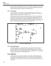
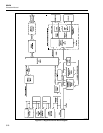
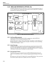
5-37. IEEE-488 INTERFACE (OPTION -05)
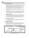
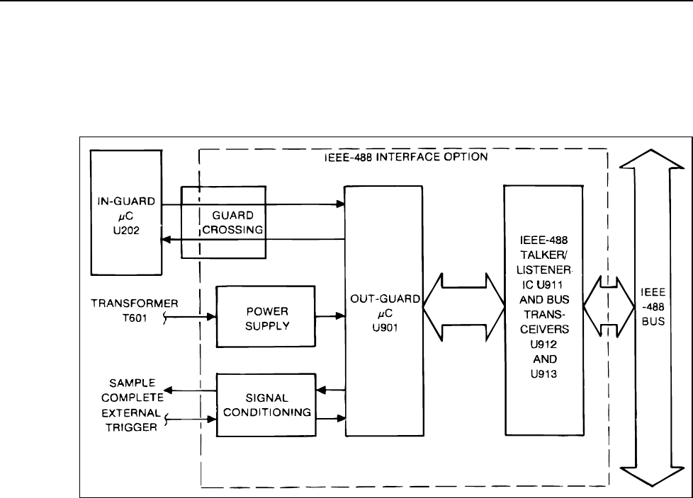
The IEEE-488 Interface has five major parts, as shown in the block diagram in Figure 5-
16. All components are contained in a single printed circuit assembly (PCA). Reference
designations are numbered in the 900 series.
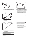
f5-16.wmf
Figure 5-16. IEEE-488 Interface Block Diagram
5-38. Out-Guard Microcomputer
The Out-Guard Microcomputer (µC) (U901) communicates with the IEEE-488
talker/listener IC (U911) and the In-Guard µC (U202).
The Out-Guard µC is similar to the In-Guard Z8 µC except that is contains 8K bytes of
ROM and 236 bytes of RAM. For futher description of the Z8 µC, refer to the heading
"In-Guard Microcimputer, " above.
5-39. Guard Crossing
The guard crossing circuit permits serial asynchronous communication between U901
and U202 while isolating the two electrically. One-half of the guard crossing circuit is
contained on the Main PCA; the other half is on the IEEE-488 Interface PCA. Operation
of the guard crossing circuit is described in an earlier heading.
5-40. Bus Interface Circuitry
The IEEE-488 bus protocol is handled by the uPD7210 IEEE-488 talker/listener IC
(U911). It is controlled by U901 as a memory mapped peripheral through an 8-bit data
bus.
Bus transceivers U912 and U913 buffer U911 from the IEEE-488 bus. They provide the
bus with the required output drive capability and receiver impedance.