


8842A
Instruction Manual
6-52
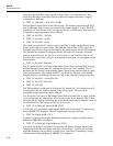
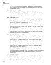
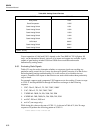
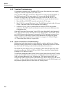
Table 6-20. Analog Control Devices
DEVICE REF. DES.
Relay Buffer U201
Quad Comparator U305
Quad Analog Switch U301
Quad Analog Switch U302
Quad Analog Switch U303
Quad Analog Switch U402
Quad Analog Switch U403
8-Bit Latch U803 *
Quad Analog Switch U804 *
Quad Analog Switch U808 *
* Option -09 only
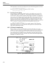
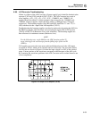
Correct operation of 8-bit latch U803, situated on the True RMS AC PCA (Option -09
only), can be determined directly since all of its inputs and outputs are available. Again,
outputs of quad analog switches U804 and U808 are not available and must be
determined by analog means.
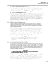
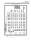
6-60. Evaluating Static Signals
Table 6-21 may be used to determine whether or not proper signals are reaching any
particular analog control device. It may also be used to quickly exercise all of the devices
before beginning analog troubleshooting if it is still unclear as to which devices are
suspect. A number of the inputs to these devices are static which makes them particularly
easy to check.
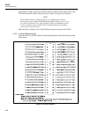
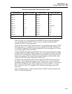
For example, suppose quad comparator U305 appears not to be working. Connect a scope
to U305-11 and step the 8842A through all functions and ranges in the following
sequence:
1. VDC: 20 mV, 200 mV, 2V, 20V, 200V, 1000V
2. VAC: 200 mV, 2V, 20V, 200V, 700V
3. 2 WIRE kΩ: 200Ω, 2k, 20k, 200k, 2M, 20M
4. 4 WIRE kΩ: 20Ω, 200Ω, 2k, 20k, 200k, 2M, 20M
5. mA DC: 200 mA, 2000 mA
6. mA AC (one range only)
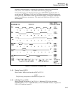
While doing this, observe the state of U305-11. As shown in Table 6-21, this 24-range
sequence will produce the following pattern at U305-11:
111010 00000 111100 1111100 000