


Chapter 5. Removing and installing components
Attention: Read the safety notices before servicing (see “Safety notices and
labels” on page xiii).
The field replaceable units (FRUs) in the SAN384B can be removed and installed
without special tools. The SAN384B can continue operating during many of the
FRU replacements if the conditions specified in the procedures are followed.
The following sections contain FRU removal and installation procedures.
v “Removing and installing the chassis door”
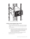
v “Removing and installing cable management finger assemblies” on page 62
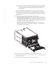
v “Removing and installing port and application blades” on page 64
v “Removing and installing blade filler panels” on page 67
v “Removing and installing a CP8 control processor blade” on page 68
v “Removing and installing a CR4S-8 core switch blade” on page 72
v “Removing and installing a power supply” on page 75
v “Removing and installing a blower assembly” on page 77
v “Removing and installing a WWN bezel and WWN card” on page 78
v “Removing and installing transceivers” on page 81
v “Removing and installing inter-chassis link (ICL) cables” on page 84
v “Removing and replacing a SAN384B chassis” on page 91
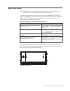
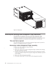
Removing and installing the chassis door
Note: The chassis door must be installed to ensure the SAN384B meets EMI and
other regulatory certifications. Additionally, if ICL cables are not used, EMI
plugs must be inserted in the ICL cable ports to meet certification standards.
Time and items required
The replacement procedure for the chassis door takes less than 5 minutes.
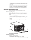
Removing the chassis door
To remove a chassis door:
1. Support the door to prevent it from falling.
2. Pull and remove the door.
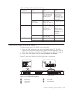
To install a chassis door, align the door and push it into place. See Figure 31 on
page 62.
© Copyright IBM Corp. 2009, 2010 61