


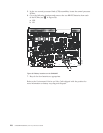
5. Remove the filler panel or port blade. Refer to “Removing a blade” on page
64 or “Removing and installing blade filler panels” on page 67.
Attention: A filler panel should be removed only when being replaced with
a port blade or new filler panel. Any slot that is not occupied by a port blade
should be occupied by a filler panel to ensure correct cooling of the chassis
and protection from dust.
6. Follow the instructions for “Installing a blade” on page 66.
7. Remove any mSFPs that are pre-installed in the new FC8-64 blade and set
them aside for later installation. See “Removing and replacing an mSFP
optical transceiver” on page 83, paying particular attention to the notices to
avoid damaging the mSFP pull tabs or mSFPs.
8. Follow the instructions for “Installing a blade” on page 66.
Note: The FC8-64 high density port blade cannot use the standard LC cables
because the pitch between optics in the new mSFP transceiver is
smaller than in standard SFPs. Patch cables and panels can be used to
attach standard size cabling to the blade if necessary. Figure 16 on page
30 illustrates the mSFP to SFP patch cable. The mSFP transceivers are
used only with the FC8-64 port blade. Narrower OM-3 LC cables are
used to connect the FC8-64. These cables are offered by several major
manufacturers. Contact your IBM representative for options regarding
different cable and patch panel configurations to simplify cable
management with higher density FC8-64 port blades.
9. Insert an OM-3 (narrow) cable into an mSFP, and then insert the mSFP/cable
unit into a port. See “Removing and replacing an mSFP optical transceiver” on
page 83, paying particular attention to the notices to avoid damaging the
mSFP pull tabs, mSFPs and cables.
10. Repeat step 8 for each port in the FC8-64 blade, proceeding in a systematic
manner to avoid tangling the cables.
11. Group and route the cables as desired. See “Managing cables” on page 42 for
additional cabling instructions.
Attention: Do not route cables in front of the exhaust vent, which is located
at the top on the port side of the chassis.
12. Verify the installation (see the appropriate section of Chapter 4, “Monitoring
system components,” on page 45). For information about how to check the
status of hardware components using the CLI, see the Fabric OS
Administrator's Guide, which is located on the product documentation CD.
13. Reinstall the chassis door. See “Removing and installing the chassis door” on
page 61.
110 SAN384B Installation, Service, and User Guide
|
|
|
|
|
|
|
|
|
|
|
|
|
|
|
|
|
|
|
|
|
|
|
|
|
|
|
|
|
|
|
|
|
|
|
|
|
|