


Table 7. Port blades available on the SAN384B (continued)
Blade label IBM blade name Feature code
FX8-24 FCIP extension blade 3890
FCoE10-24 Fibre Channel over Ethernet blade 3880
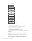
The SAN384B uses the following port numbering for each of the blades that can be
installed in the chassis. See illustrations of the different blades in Appendix D,
“Blade port numbering,” on page 137. Refer to Implementing an IBM/Brocade SAN
with 8 Gbps Directors and Switches, (an IBM Redbook), SG24-6116 for more details
on port numbering and other technical information.
Note: Blades are installed in a horizontal orientation in the SAN384B chassis, so
the normal top of the blade is oriented to the left, and the normal bottom of
the blade is oriented to the right when the blades are installed in the chassis.
v FC8-16 port blade - Ports are numbered from 0 through 15 from right to left.
v FC8-32 port blade - Ports are numbered from 0 through 15 from right to left on
the lower row of ports and 16 through 31 from right to left on the upper row of
ports.
v FC8-48 port blade - Ports are numbered from 0 through 23 from right to left on
the lower row of ports and 24 through 47 from right to left on the upper row of
ports.
v FC8-64 port blade - Ports are numbered from 0 through 31 from right to left on
the lower row of ports and 32 through 63 from right to left on the upper row of
ports. See Figure 54 on page 138 for an illustration of the blade. Trunking groups
are permitted with up to eight ports per group. Trunking groups are as follows:
0-7, 8-15, 16-23, 24-31, 32-39, 40-47, 48-55, and 56-63.
v FC10-6 port blade - Ports are numbered from 0 through 5 from right to left.
v FR4-18i router blade - The 16 physical Fibre Channel ports are numbered from 0
through 15 from right to left. The two GbE ports, numbered GE0 and GE1, are
located to the right of the Fibre Channel ports. These ports, when fully
configured, enable 16 VE_ports or VEX_ports and appear in the switchShow
command as ports 16 through 31.
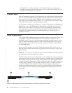
v FX8-24 FCIP extension blade - The port numbering scheme is fairly complex for
this blade, but is displayed for reference on the blade itself in a diagram towards
the right end of the blade (see Figure 57 on page 139). There are twenty-four
physical ports. Twelve FC ports are located towards the right end of the blade,
with ports 0 through 5 in the lower row, and ports 6 through 11 in the upper
row. Two 10 Gigabit Ethernet (10GbE or XGE) ports are located in the lower row
of ports and are numbered 0 and 1, from right to left. Ten GbE ports are located
towards the left end of the blade, with eight clustered to the far left, and the
remaining two located above the two 10GbE ports. The GbE ports 0 through 3,
numbered from right to left are located in the lower row to the far left side of
the blade. Ports 4 and 5 are located above the two 10GbE ports, and ports 6
through 9 (numbered right to left) are in the top row above ports 0 through 3.
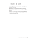
Up to three FC trunking groups. The three groups are defined as:
– Trunk group 0: FC ports 0, 1
– Trunk group 1: FC ports 6, 7
– Trunk group 2: FC ports 2, 3, 4, 5, 8, 9, 10, 11
–
Chapter 2. Installing a SAN384B in a cabinet 29
|
|
|
|
|
|
|
|
|
|
|
|
|
|