


7. Release the two spring-loaded pins on the under side of the load plate and
slide the middle section as far as possible into the cabinet until it stops. The
chassis should not move with the middle section.
Note: If the chassis is not carefully centered over the middle section, the
weight of the chassis may prevent the middle section from sliding.
Adjust the alignment if needed.
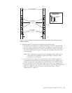
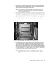
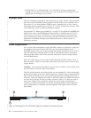
8. Release the spring-loaded pin closest to the cabinet one more time, and slide
the middle section to its full extension. Make sure the spring-loaded pin snaps
back into place. The gap between the end of the load plate middle section and
the port side exhaust kit shelf should be no more than 2.5 cm (1 in.). If the
gap is larger than this, either the lift tool is not positioned close enough to the
cabinet, or the load plate middle section is not fully extended. Adjust as
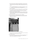
needed. Figure 12 shows a view from inside the cabinet, with the middle
section of the lift tool load plate extended, and the chassis centered on the
load plate.
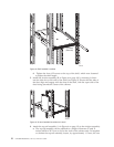
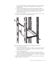
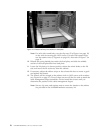
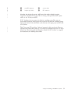
9. Carefully slide the chassis into the cabinet between the shelf and the upper
edge of the exhaust kit duct assembly until the chassis rests securely on the
shelf. Figure 13 on page 26 shows a view from outside the cabinet with the
middle of the load plate fully extended and the chassis pushed approximately
half way into the cabinet. Reposition the nut clips installed earlier if necessary.
Push the chassis all the way into the cabinet until the flanges on the port side
of the chassis are firmly against the cabinet vertical rails.
Note: If necessary, adjust the height of the load plate to allow a smooth
transfer of the chassis from the extended load plate to the top of the
shelf.
Figure 12. Load plate extended inside the cabinet to the exhaust kit shelf
Chapter 2. Installing a SAN384B in a cabinet 25