


Installation guidelines
Follow these general installation guidelines:
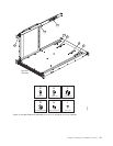
1. Provide a space that is 9 rack units (9U) high, 61.19 cm (24.09 in.) deep, and
43.74 cm (17.22 in.) wide. 1U is equal to 4.45 cm (1.75 in.).
2. Ensure that dedicated electrical branch circuits with the following requirements
are met:
v 200 – 240 VAC, 50–60 Hz (two branch circuits)
v Two cables for the 200 - 240 VAC service
v Power supply standards (“Power specifications”) are met
v Protected by a circuit breaker in accordance with local electrical codes
v Supply circuit, line fusing, and wire size adequate to the electrical rating on
the chassis nameplate
v Location close to the chassis and easily accessible
v Grounded outlets installed by a licensed electrician and compatible with the
power cords
Attention: To maximize fault tolerance, connect each power cord to a
separate power source.
3. To ensure adequate cooling, plan to install the chassis with the port side facing
the aisle where exhaust air is released (usually called the service aisle). This
prevents the fans from pulling in heated exhaust air.
4. Plan for managing the cables before you install the chassis. A fully populated
SAN384B will have a large number of cables that must be carefully routed to
minimize problems with installation and replacement of components, and in
order to maintain the minimum bend radius required for optical cables. Due to
port density and the potentially large number of cables, if cables are not routed
to the sides, then removal and replacement of blades and other components
may be difficult to accomplish. Refer to “Managing cables” on page 42 for more
specific information. You can manage the cables in a variety of ways, such as:
v Routing the cables through the vertical cable management finger assemblies
installed on either side of the chassis
v Routing the cables out to either side of the chassis
v Routing the cables through the cable channels on the sides of the cabinet
v Using patch panels
5. Ensure that the following are available for configuration:
v Workstation with an installed terminal emulator, such as HyperTerminal
v Serial cable (provided)
v Three Ethernet cables (including one spare)
v Access to an FTP server for backing up the switch configuration or collecting
supportsave output data (optional)
v SFPs and compatible cables
6. Ensure that the air intake vents have a minimum of 2 inches of airspace.
7. Ensure that the air temperature on the air intake side is less than 40°C (104°F )
during operation.
Chapter 2. Installing a SAN384B in a cabinet 13