


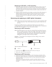

Replacing an SFP, SFP+, or XFP transceiver
1. Position the optical transceiver so that the key is oriented correctly to the port.
Insert the transceiver into the port until it is firmly seated and the latching
mechanism clicks. Transceivers are keyed so that they can only be inserted with
the correct orientation. If a transceiver does not slide in easily, ensure that it is
correctly oriented.
2. Position a cable so that the key (the ridge on one side of the cable connector) is
aligned with the slot in the transceiver. Insert the cable into the transceiver
until the latching mechanism clicks. Cables are keyed so that they can be
inserted in only one way. If a cable does not slide in easily, ensure that it is
correctly oriented.
Removing and replacing an mSFP optical transceiver
Note: mSFP optical transceivers should not be inserted into ports intended for SFP
or SFP+ transceivers. They will be faulted on power-up For Fabric OS 6.4.0
and later.
To replace an mSFP transceiver, complete the following steps. Note that it is
recommended that the optical cable should be either removed from or inserted into
the mSFP while the transceiver is out of the switch or blade.
Removing an mSFP transceiver
Note: The mSFP transceivers are used only with the FC8-64 port blade. Narrower
OM-3 LC cables are used to connect the FC8-64. These cables are offered by
several major manufacturers. Contact your IBM representative for options
regarding different cable and patch panel configurations to simplify cable
management with higher density FC8-64 port blades.
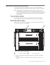
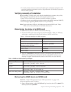
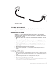
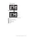
Attention: The pull tabs are not designed to be bent. Doing so may result in
damage to the pull tab.
1 Pull tab 2 mSFP transceiver
1. Grasp the pull tab 1 firmly and pull the unit out of the port.
2. Remove the cable from the transceiver.
Replacing an mSFP transceiver
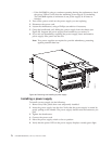
1. Insert the cable into the new transceiver until the latching mechanism clicks.
2. Position the optical transceiver so that the key is oriented correctly to the port.
Insert the transceiver into the port until it is firmly seated and the latching
mechanism clicks.
Transceivers are keyed so that they can only be inserted with the correct
orientation. If a transceiver does not slide in easily, ensure that it is correctly
oriented.
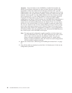
1 2
b768ig052
Figure 43. Optical mSFP transceiver
Chapter 5. Removing and installing components 83
|
|
|
|
|
|
|
|
|
|
|
|
|
|
|
|
|
|
|
|
|
|
|
|
|
|
|
|
|
|
|
|
||||
|
|
|
|
|
|
|
|
|
|
|