


Time and items required
The installation procedure for the core switch blade takes approximately 30
minutes. The following items are required for the core switch blade replacement:
v ESD grounding strap
v #2 Phillips screwdriver
v Replacement CR4S-8 core switch blade.
Verifying the necessity of installation
Confirm that you need to replace the core switch blade before continuing. The
following events might indicate that a core switch blade is faulty:
v The status LED on the core switch blade is lit amber, or the power LED is not
lit.
v The slotShow command does not show that the core switch blade is enabled.
v The haShow command indicates an error.
v Any of the following messages display in the error log:
– “Slot unknown” message relating to a core switch blade slot
– core switch blade errors or I
2
C timeouts
– FRU: FRU_FAULTY messages for a core switch blade
– Configuration loader messages or “Sys PCI config” messages
– Generic system driver messages (“FABSYS”)
– Platform system driver messages (“Platform”)
– Error messages that indicate a problem with a core switch blade
– Function fail messages for the core switch blade master
For more information about error messages, refer to the Fabric OS Message
Reference.
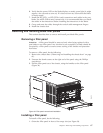
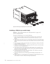
Removing a CR4S-8 core switch blade
The SAN384B continues to operate while a core switch blade is being replaced.
Attention: Follow ESD precautions (see “ESD precautions” on page xviii)
whenever handling blades.
Note: The CR4S-8 blade is compatible only with the SAN384B.
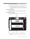
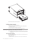
1. Remove the chassis door (see “Removing and installing the chassis door” on
page 61).
2. Power off the blade by sliding the slider switch in the left ejector to the right,
to the off position. Do not eject the blade until the power LED has gone off and
you have completed the next two steps.
3. Disconnect all cables from the faulty core switch blade. If ICL cables are not
used, remove the EMI plugs from the cable sockets.
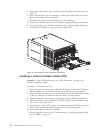
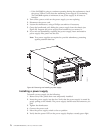
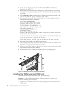
4. Unscrew the thumbscrews from both ejectors using the Phillips screwdriver.
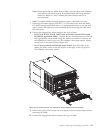
5. Open both ejectors simultaneously to approximately 45 degrees and pull the
core switch blade out of the chassis (Figure 36 on page 74).
Chapter 5. Removing and installing components 73
|
|
|
|