


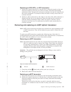
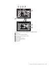
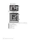
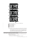

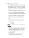

1 Chassis 1 (SAN384B)
2 Core switch blades (CR4S-8)
3 Chassis 2 (SAN384B)
4 Chassis 3 (SAN384B)
5 ICL connector (ICL 1)
6 ICL connector (ICL 0)
Note: For clarity, the two sets of cables are drawn differently (solid and dashed) in
Figure 47 on page 89 through Figure 49. Also note that one set is connected
to only the blades in the "low order" slots (slot 3 in the SAN384B and slot 5
in the SAN768B) and the other set is connected to the blades in the "high
order" slots (slot 5 in the SAN384B and slot 8 in the SAN768B). Keeping the
sets apart in this manner minimizes the cable confusion.
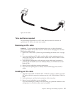
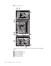
Removing and replacing a SAN384B chassis
This section describes how to remove and replace the SAN384B chassis (with its
backplane). The basic steps are:
v “Verifying need for replacement” on page 92
v “Recording critical SAN384B and SAN information” on page 92
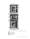
5
6
2
5
2
2
5
6
6
3
1
4
384b060
Figure 49. 3-way ICL cable connections between three SAN384B chassis.
Chapter 5. Removing and installing components 91
|
|
|
|
|
|
|
|
|
|
|