


15. Release the lift tool wheel brake, and move the lift tool away from the cabinet.
16. Lower the load platform to its lowest position.
17. Use the lift tool to relocate the chassis to the desired location.
Installing the replacement chassis
Attention: Refer to “Rack safety” on page xix before starting the installation.
svc00169
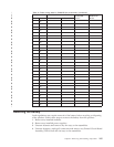
55 kg ( 121.2 lbs)
>55kg (121.2 lb)
CAUTION:
The weight of this part or unit is more than 55 kg (121.2 lb). It takes
specially trained persons, a lifting device, or both to safely lift this
part or unit. (C011)
The following instructions require that the port-side exhaust kit is already installed.
If the rack does not have this shelf and exhaust duct installed, refer to “Installing
the port-side exhaust kit” on page 18 for complete instructions.
1. Follow the steps in “Unpacking the SAN384B” on page 16 to unpack the
replacement chassis.
2. Follow the steps in “Installing the SAN384B into the cabinet” on page 24 to
complete the installation of the replacement chassis. You can either install the
empty chassis now, or first install the components steps 1-7 (“Installing
components into the new chassis”) before completing the chassis installation.
Note: If you anticipate that the replacement chassis may be shipped to a new
location while installed in the cabinet, it is recommended that you attach
the shipping brackets to any replacement chassis. These shipping
brackets consist of flat mounting plates that are attached to the sides of
the chassis at the blower assembly end, and L-brackets that attach to the
mounting plates and the cabinet vertical rails.
Installing components into the new chassis
Attention: Follow ESD precautions (“ESD precautions” on page xviii) whenever
handling components.
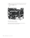
1. Replace the WWN cards and WWN bezel (“Installing the WWN bezel and
WWN card” on page 80.
2. Replace the blower assemblies (“Installing a blower assembly” on page 78).
3. Replace the power supplies (“Installing a power supply” on page 76).
4. Replace the control processor blades (“Installing a control processor blade
(CP8)” on page 70).
5. Replace the core switch blades (“Installing a CR4S-8 core switch blade” on
page 74).
6. If ICL cables are not used, insert EMI plugs in the ICL sockets in the core
switch blades (CR4S-8).
7. Replace the port and application blades or filler panels (“Installing a blade”
on page 66 and “Installing a filler panel” on page 67).
8. If the chassis is not yet installed in the rack, follow the steps in “Installing the
SAN384B into the cabinet” on page 24.
9. Replace the cable management fingers (“Installing a cable management finger
assembly” on page 63).
Chapter 5. Removing and installing components 99