


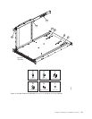
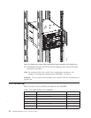

6-32 screws (I-3 in Figure 6 on page 19) and adjust the top-rail assembly to
the desired length. The length will be approximately the length of the
adjustable shelf.
b. Insert the top-rail assembly down into the air-duct assembly and then
secure the top-rail assembly to the air-duct assembly with two 6-32 screws,
one screw on each side of the air-duct assembly (I-1 and I-2 in Figure 6 on
page 19). Tighten screws according to specifications under “Torque
requirements” on page 20.
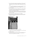
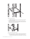
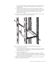
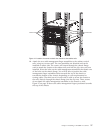
7. Secure the top-rail assembly to the cabinet with four 10-32 screws, two screws
on each end of the top-rail assembly (see Figure 10).
a. For rails with round holes:
Use two 10-32 screws with washers (E in Figure 6 on page 19) on each end
of the top rail assembly. Tighten screws according to specifications under
“Torque requirements” on page 20.
b. For rails with square holes:
Use the two standard 10-32 screws (D in Figure 6 on page 19) with blue
Loctite on the threads and alignment washers (H in Figure 6 on page 19) on
each end of the top rail assembly. Tighten screws according to specifications
under “Torque requirements” on page 20.
8. Tighten the two 6-32 screws (I-3 in Figure 6 on page 19) that were loosened in
step 6a to adjust the top rail length.
384b037
Figure 10. Installing the top rail assembly to the duct assembly and cabinet rails
Chapter 2. Installing a SAN384B in a cabinet 23