


v FCoE10-24 FC over Ethernet blade - The 24 physical ports are numbered 0
through 11 from right to left on the lower row of ports and 12 through 23 from
right to left on the upper row of ports.
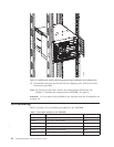
Chassis slots
Slots are numbered 1 through 8, from bottom to top of the chassis when facing the
port side of the SAN384B. Control processor blades (CP8) can be installed only in
slots 4 and 5. Core switch blades (CR4S-8) can be installed only in slots 3 and 6.
Port blades can be installed only in slots 1, 2, 7, and 8. Unused slots must be filled
with blade filler panels to maintain adequate cooling.
See Appendix D, “Blade port numbering,” on page 137 for different SAN384B port
blades. Also refer to the IBM Redbook, Implementing an IBM/Brocade SAN with 8
Gbps Directors and Switches, SG24-6116, for more comprehensive information on
port numbering and area port numbering, and other technical information. This
publication is available through www.redbooks.ibm.com/. Search by title or
publication number.
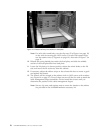
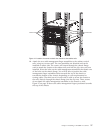
Cable organization
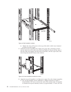
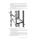
Two vertical cable management finger assemblies (shown in Figure 32 on page 63)
are attached to the rack vertical rails. They are not attached directly to the
SAN384B chassis. This pair of cable management finger assemblies can be used to
keep the cables from hanging down in front of other blades, and to route them
away from the exhaust vent of the port-side exhaust kit, which is located below
the SAN384B chassis.
Route the cables across in front of the blades, keeping the LEDs visible. Leave at
least one meter of slack for each fiber optic cable to provide room to remove and
replace blades.
Attention: Do not route the cables in front of the air exhaust vents, located at the
top and bottom of the port side of the chassis.
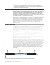
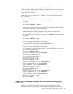
The FC8-64 high density port blade cannot use the standard LC cables because the
pitch between optics in the new mSFP transceiver is smaller than in standard SFPs.
Patch cables and panels can be used to attach standard size cabling to the blade if
necessary. Figure 16 illustrates the mSFP to SFP patch cable. The mSFP transceivers
are used only with the FC8-64 port blade. Narrower OM-3 LC cables are used to
connect the FC8-64. These cables are offered by several major manufacturers.
Contact your IBM representative for options regarding different cable and patch
panel configurations to simplify cable management with higher density FC8-64
port blades.
2 3
4
1
b768ig045
Figure 16. Cable design for the mSFP patch cables for the FC8-64 high density port blade
30 SAN384B Installation, Service, and User Guide
|
|
|
|
|
|
|
|
|
|
|
|
|
|
|
|
|
|
|
|
|
|
|
|
|
|
|
|
|
|
|