


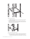
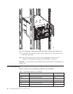

14. Attach the two cable management finger assemblies to the cabinet vertical
rails, using two screws each. The two assemblies are identical and can be
installed on either side. The screws will extend through the chassis flange
used to attach the chassis to the cabinet rails, and into the clip nuts you have
installed. Select the holes on the cable management assemblies that match two
of the holes on the chassis flange. You will be able to position the cable
management finger assemblies either towards the top of the chassis or
towards the bottom of the chassis, depending on your requirements for
routing cables. The third screw for each side is used to secure the chassis to
the rails, directly through the chassis flange into the clip nuts. These screws
do not attach the cable management assemblies to the chassis or rack.
Figure 15 on page 28 shows the cable management fingers positioned towards
the top of the chassis.
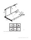
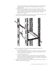
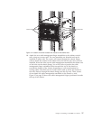
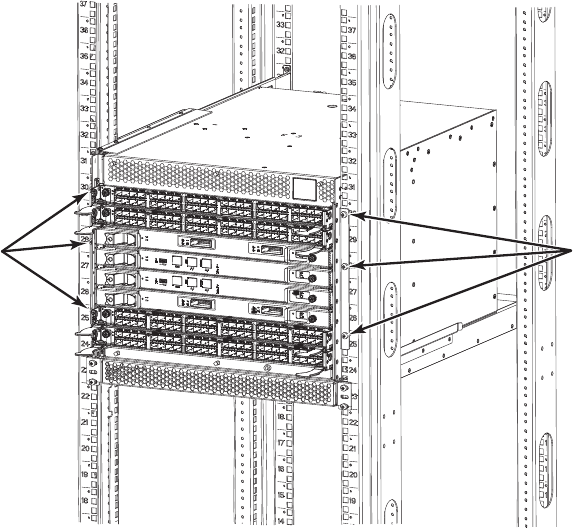
384b038
Install screws
Install screws
Figure 14. Location of screws to attach the chassis to the cabinet rails
Chapter 2. Installing a SAN384B in a cabinet 27