


Chapter 3 Basic Functions
II-9
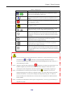
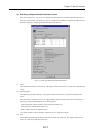
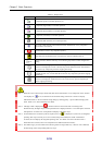
Table 3-2 Display Icons
Icon Status
l, etc.
These icons are monitoring state where all disk array components are in normal
status. The icon’s shape differs by disk array type.
This icon is a monitoring state where an event or fault (except critical fault)
that needs “maintenance” occurred in any disk array components. (Note 1
and 2)
This icon is a monitoring state where a critical fault occurred in any disk
array components. (Note 2)
This icon is a monitoring state where “threshold excess” occurred in any pool
for snapshot. (Note 3)
, etc.
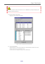
These icons show that the disk array is in monitoring stop status or under
configuration setting. The icon’s shape differs by disk array type.
This shows monitoring stop status or under configuration setting.
If this icon is displayed, an event or fault (except critical fault) that needs
“maintenance” occurred in any disk array components just before stopping
monitoring.
This shows monitoring stop status or under configuration setting.
If displaying this icon, a critical fault has occurred in any disk array
components just before stopping monitoring.
This shows monitoring stop status or under configuration setting.
If displaying this icon, “threshold excess” has occurred in any pool for
snapshot just before stopping monitoring.
This icon indicates that disk array components are not being monitored.
If this icon is displayed, the SVP settings of the target disk array include an
incorrect IP address setting, or the target disk array could not be connected to
the iSM server.
Note 1 If an event or fault (except critical fault) that needs “maintenance” occurred, the disk array icon can be
switched between “ ” and “ ”. Switching is executed at [Display Maintenance State] in
environment setting dialog by selecting [File] → [Environment Settings] from the menu. Refer to 5.2
“Client Start/Stop” for details.
Note 2 Although a component fault is displayed by “ ”, whether this icon deserves the critical fault or not is
decided at a higher layer, and the icon according to the status is displayed. Please refer to 3.2.2
“Description of screen and operation” about the component status icon and display in higher layer.
Note 3 If a threshold excess occurred in pool for snapshot, the icon “ ” is displayed. If, however, the
integrated operating state of a disk array component is faulty or an event or fault (except critical fault)
that needs “maintenance” occurred, the icon displays the integrated operating state. For details on
actions to be taken when a threshold excess occurred, refer to the “Snapshot User's Manual (Function
Guide)” (IS030).
Note 4 The shade of icon indicates the monitoring state of target disk array. If icon is gray, the monitoring of
target disk array stops.