


14 TASCAM HS-4000
2 − Names and functions of parts
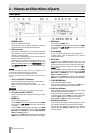
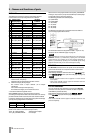
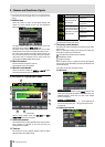
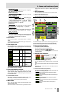
PARALLEL connector
The PARALLEL connector on the rear panel allows external
ontrol of this unit. The pin assignments are as follows. c
Pin
No.
Timeline / Take /
Playlist [Single]
Playlist [Dual]
RC-SS20
PonMode
I/O
1 GND GND GND
2 PLAY PLAY A FLASH 1
I
3 STOP STOP A FLASH 2
I
4 RECORD (Reserved) FLASH 3
I
5 SKIP FWD SKIP FWD FLASH 4
I
6 SKIP BWD SKIP BWD FLASH 5
I
7 (Reserved) STOP B STOP
I
8 FADER_START FADER_START A FADER_START
I
9 TALLY_BC_STOP TALLY_PAUSE B TALLY_BC_STOP
O
10
TALLY_PAUSE /
TALLY_BC_PAUS
E
TALLY_PAUSE A
TALLY_PAUSE A /
TALLY_BC_PAUS
E
O
11 TALLY_RECORD (Reserved) RESERVED
O
12 TALLY_STOP TALLY_STOP A TALLY_STOP
O
13 TALLY_PLAY TALLY_PLAY A TALLY_PLAY
O
14
REMOTE_SELECT
,
H or Open
REMOTE_SELECT
,
H or Open
REMOTE_SELEC
T, L
I
15 PAUSE PAUSE FLASH 6
I
16 (Reserved) PLAY B FLASH 7
I
17 AUX1, FF AUX1, FF FLASH 8
I
18 AUX2, REW AUX2, REW FLASH 9
I
19 AUX3, MARK AUX3, MARK FLASH 10
I
20 (Reserved) A/B SELECT FLASH_PAGE
I
21
TALLY_BC_STAN
DBY
TALLY_PLAY B
TALLY_BC_STAN
DBY
O
22 TALLY_BC_CM TALLY_STOP B
TALLY_CF1 /
TALLY_BC_CM
O
23 TALLY_ONLINE TALLY_ONLINE A TALLY_ONLINE
O
24 TALLY_BC_END TALLY_ONLINE B
TALLY_CF2 /
TALLY_BC_END
O
25 +5V +5V +5V
I Command input for transport control
Internal circuit, +5V pull-up
Operates with low commands of 50 msec or more
O Command output, for tally output
The internal circuit is open collector (10 Ω output
impedance)
Low command output when operating
20 V dielectric strength, 35 mA maximum current
*
+5V: 50 mA maximum supplied current
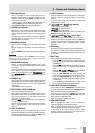
When REMOTE Select (pin 14) is set to high, it functions
according to the operation mode and can be used as an ordinary
parallel controller. When set to low, flash start mode is enabled.
In addition, depending on the high/low setting of the Flash Page
pin 20), the key assignments are as follows. (
Pin 14 Pin 20 Flash start take
Low High 1–10
Low Low 11–20
TALLY_BC_*: Use menu setting to switch output (OFF, ON)
(When an RC–SS20 is connected set output to OFF.)
TALLY_BC_STOP/CM/END: 250 msec pulse output
TALLY_BC_STANDBY/PAUSE: Level output
When the main unit’s playlist mode is set to [dual], and REMOTE
Select (pin 14) is set to hi, use pin 20 (A/B SELECT) to select player
A or B (Hi for player A and Lo for player B).
The following pins affect the selected player.
Pin 5 (SKIP FWD)
Pin 6 (SKIP BWD)
Pin 15 (PAUSE)
Pin 17 (AUX1)
Pin 18 (AUX2)
P
in 19 (AUX3)
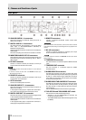
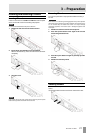
The following example is of a connection that uses a fader to
start and stop playback of this device.
For information about the assignment of AUX 1–3 (pins 17–19)
functions, see the “PARALLEL page” on page 76.
NOTE
When controlling this unit with an external device that is connected to the
PARALLEL connector, by simultaneously inputting PLAY and RECORD
signals while this unit is stopped, you can start recording immediately. In
addition, by simultaneously inputting PLAY and RECORD signals during
playback in timeline mode, you can start overwriting the recording.
RS–232C connector
The RS–232C connector on the rear panel can be connected to
an RS–232C connector on a computer to allow control of this
unit from that computer.
Make settings related to communication on the
RS–232C page
of the
REMOTE SETUP screen. (See “RS–232C page” on page 77.)
NOTE
・ RS–232C connector functions will be supported in a future firmware
version update.
・ Please contact TASCAM customer support for information about this
unit’s RS–232C command protocol.
RS–422 connector
You can control this unit remotely by connecting the RS–422
connector on its rear panel to a controller or editor compatible
with SONY P2 protocol (RS–422).
Make settings related to operation on the
REMOTE SETUP
screen
RS–422 page. (See “RS–422 page” on page 77.)
NOTE
Please contact TASCAM customer support for information about this unit’s
protocol compatibility.