


12 TASCAM HS-4000
2 − Names and functions of parts
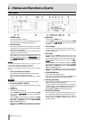
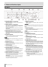
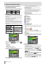
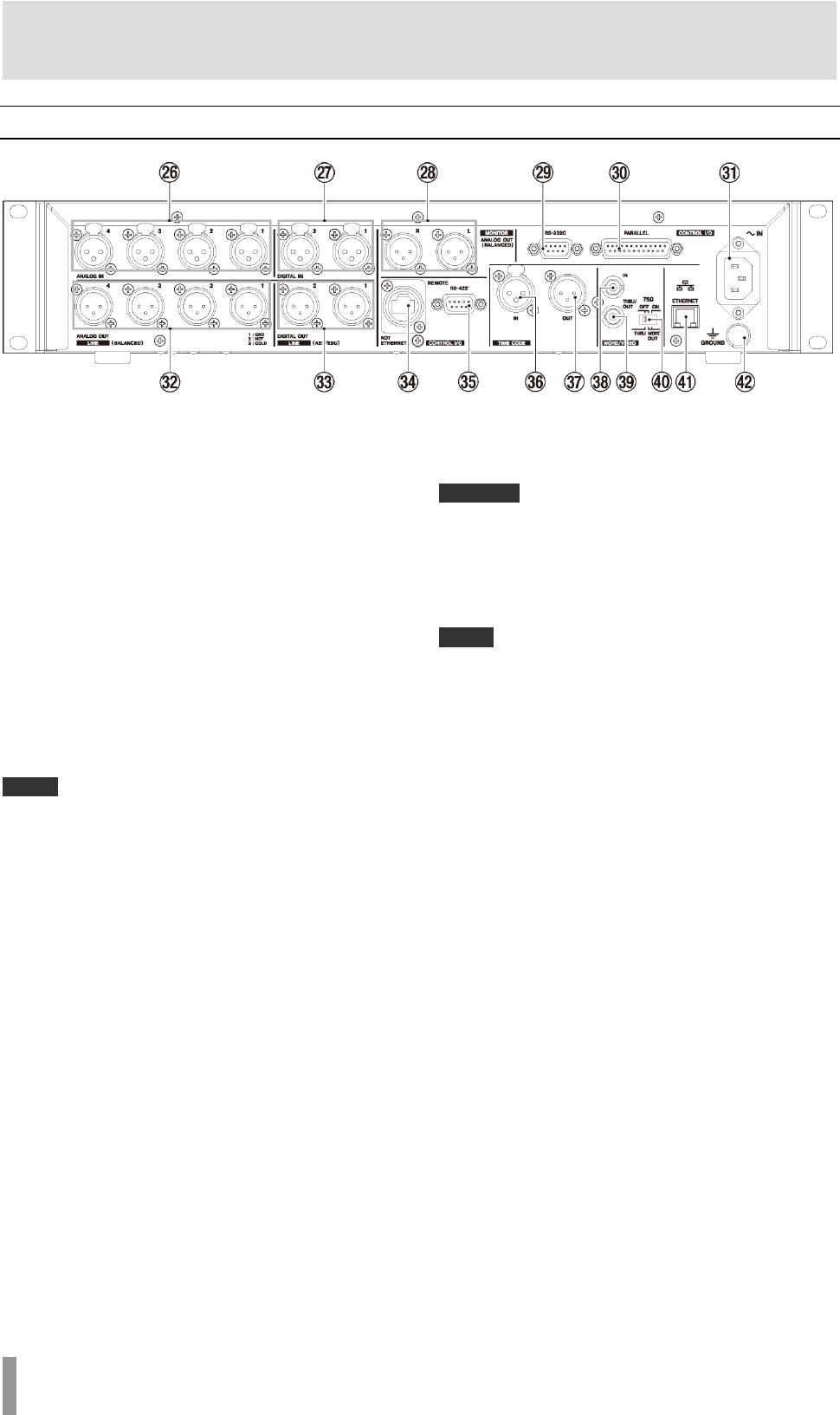
Rear panel
26 ANALOG LINE IN 1–4 connectors
These XLR connectors are balanced analog line inputs. (1:
GND, 2: HOT, 3: COLD)
27 DIGITAL LINE IN 1–2 connectors
Use these balanced XLR connectors (1 and 2) for digital
audio input in AES3-2003/IEC60958-4 (AES/EBU) or
IEC60958-3 (S/PDIF) format.
Sampling frequencies of 88.2 and 96 kHz are transmitted at
double speed.
The built-in sampling rate converter can handle 32–192 kHz.
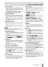
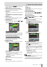
28 MONITOR ANALOG OUT L/R connectors
These balanced analog XLR connectors output the left and
right signals from the internal monitoring mixer. (1: GND, 2:
HOT, 3: COLD)
29 RS-232C connector
Connect an external controller, for example, to this 9-pin
D-sub connector for RS-232C serial control.
NOTE
・ The RS-232C connector will be made functional in a future firmware
version update.
・ It cannot be used at the same time as the RS-422 connector. (See
“RS-232C page” on page 77.)
30 PARALLEL connector
Connect an external controller, for example, to this 25-pin
D-sub parallel control connector.
31 AC IN connector
Connect the included power cord here.
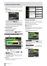
32 ANALOG LINE OUT 1–4 connectors
These XLR connectors are balanced analog line outputs. (1:
GND, 2: HOT, 3: COLD)
In dual playlist mode, player A outputs from connectors 1
and 2, while player B outputs from connectors 3 and 4.
33 DIGITAL LINE OUT 1/2 connectors
These XLR connectors are balanced outputs for digital audio
in AES3-2003/IEC 60958-4 (AES/EBU) format.
Sampling frequencies of 88.2 and 96 kHz are transmitted at
double speed.
In dual playlist mode, player A outputs from connector 1,
while player B outputs from connector 2.
34 REMOTE connectors
Connect a TASCAM RC-HS32PD remote control (sold
separately) here.
CAUTION
This is not an Ethernet connector (LAN, etc.). Never connect this to a network
using an Ethernet cable. Doing so could damage this unit or equipment in the
network.
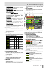
35 RS-422 connectors
Connect an external controller, for example, to this 9-pin
D-sub connector for RS-422 serial control.
NOTE
It cannot be used at the same time as the RS-232C connector. (See “RS-422
page” on page 77.)
36 TIMECODE IN connector
This XLR connector is a balanced input for SMPTE timecode
input.
37 TIMECODE OUT connector
This XLR connector is a balanced output for SMPTE
timecode output.
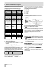
38 WORD/VIDEO IN connectors
This BNC-type connector is for input of a word clock signal
(44.1 kHz, 48 kHz, 48 kHz pull-down, 48 kHz pull-up, 88.2 kHz,
96 kHz) or a video reference signal (NTSC/PAL black burst
signal, HDTV Tri-Level signal). Use the switch to set whether
or not to terminate with 75 Ω.
39 WORD/VIDEO THRU/WORD OUT connector
This BNC-type connector is for output of a word clock signal
(thru, 44.1 kHz, 48 kHz, 48 kHz pull-down, 48 kHz pull-up,
88.2 kHz, 96 kHz) or a video reference signal (IN connector
signal thru only).
Use the THRU/WORD OUT switch to set the signal output.
40 75Ω OFF/ON and THRU/WORD OUT switch
Use this switch to make the following settings.
・ Whether or not the WORD/VIDEO IN connector has
termination resistance (75 Ω)
・ The WORD/VIDEO output THRU/OUT setting (OUT is only
for WORD)