


Introduction: Control Reference Guide
27
Introduction
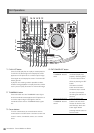
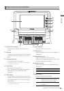
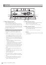
14.ANALOG COMPOSITE VIDEO IN connector
Inputs analog composite video signals.
15.ANALOG COMPONENT VIDEO OUT connectors
Inputs analog composite video signals during output
of HD signals. When SD is selected as the output
signal, three composite signals are output.
Setup menu 643 OUT MODE SEL determines the
signals that are output.
◆ NOTE:
• Use only shielded cable for cables (except the AC cable)
that are connected to the rear panel. Cables connected to
serial digital signal connectors (SDI IN/OUT connectors)
should be double shielded cables.
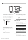
■ Basic Setup
Make sure that menu No. 882 DIF IN CH and No. 883 DIF OUT
CH on this unit are set to “AUTO.”
◆ NOTE:
• Only signals that comply with the format selected in menu No. 020
SYS FORMAT can be input. When the SYS FORMAT is 480i (576i at
50 Hz), operations are limited to menu No. 024 REC FMT (SD)
settings.
• The selected recording format and the format of a recording on an
inserted P2 card determine the output format.
* Select CH1/CH2 or CH3/CH4 as the output audio channels (in
DVCPRO/DV).
■ Precautions
• Connect this unit to only one other device.
• If the E-92 warning (1394 INITIAL ERROR) appears,
reconnect the connecting cable or turn the power off and
back on again.
• AV signals may be disrupted when connected devices are
turned on and off or when the interface cable is connected
or disconnected.
• It may take the system a few seconds to stabilize after
switching input signals or changing modes. Start recording
after the system has stabilized.
• The following applies to recordings made via the IEEE 1394
digital interface as well as to the signals it outputs.
- The audio level control knobs on the front panel do
not work.
- The settings in menu No. 680 and 681 regarding
blanking periods are ignored.
- Video and audio recording and EE type video and
audio of signal inputs other than 1x speed playback
signals are not guaranteed.
• The following applies to video input via the IEEE 1394 digital
interface.
- In the EE mode, SDI, analog video output signals
and time codes become irregular. Do not use these
signals for recording.
• Unprocessed video and audio signals are output via the
IEEE 1394 digital interface during SLOW and STILL
playback. When monitored on another device, these video
and audio signals may sound different than when played
back on this unit. Do not start up any other application
program when this unit is connected to other devices during
nonlinear editing. Such applications could adversely affect
the video output by such a device during nonlinear editing.
◆ NOTE:
Observe the following when connecting an IEEE 1394 cable
(separately sold). (An incorrect connection may damage this unit
or external devices.)
•Turn off all connected devices before connecting or disconnecting
IEEE1394 cables.
Connect all devices provided with a ground connector to ground (or
to a common ground).
•When connecting the unit to a device with a 4-pin connector,
connect the cable to the 6-pin connector on this unit first.
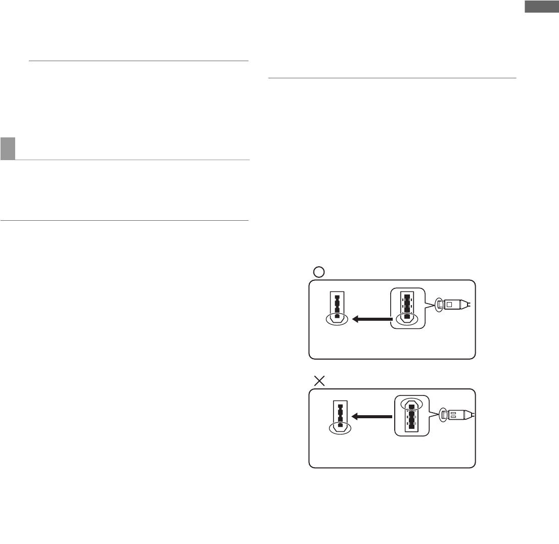
•Be sure to correctly connect an IEEE1394 cable to a connector.
• When connecting a cable to a 6-pin IEEE1394 connector, make sure
that it mates properly with the connector.
•When connecting this unit to an external device, first connect the
IEEE1394 cable to the external unit and then to this unit.
Connecting the cable to this unit first may damage it by the static
electricity generated.
•AVC-Intra 50 and AVC-Intra 100 (optional) recording and playback
do not support input/output via the IEEE 1394 connector.
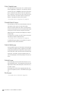
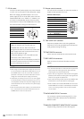
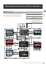
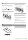
IEEE 1394 Digital Interface
IEEE1394
connector
IEEE1394
cable plug
(This way)
IEEE1394
connector
IEEE1394
cable plug
(Not this way)