


118
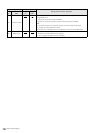
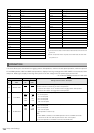
Setup: Item Settings
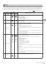
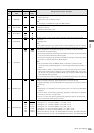
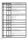
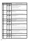
504 RUN MODE
0000
0001
REC
FREE
Specifies an operating mode that advances the internal time code generator.
0: The internal time code generator is advanced only during recording.
1: When the power is on, the internal time code generator is advanced regardless of
operating mode.
505 TCG REGEN
0000
0001
0002
TC&UB
TC
UB
Specifies the signal to regenerate when the time code generator (TCG) is in the REGEN
mode.
0: Regenerates both the time code and the user bit
1: Regenerates only the time code
2: Regenerates only the user bit
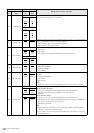
507 EXT TC SEL
0001
0002
0003
EXT_L
SLTC
SVITC
Specifies the time code used when an external time code is used.
0: LTC of the TIME CODE IN connector
1: LTC data attached to serial signal input to HD SDI IN
2: VITC data attached to serial signal input to HD SDI IN
NOTE:
When SLTC and SVITC are set, the VITC in the input video signal is used when an analog
composite or SD SDI input signal is selected. When 1394 is selected as the input signal,
the IEEE 1394 digital input signal time code is used regardless of this setting.
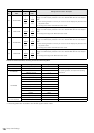
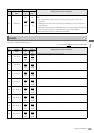
508 BINARY GP
0000
0001
0002
0003
0004
0005
0006
0007
000
001
010
011
100
101
110
111
Specifies user bit usage in time code generated by the TCG.
0: NOT SPECIFIED (character set not specified)
1: ISO CHARACTER (8-bit character set complying with ISO646 and ISO2022)
2: UNASSIGNED 1 (undefined)
3: UNASSIGNED 2 (undefined)
4: UNASSIGNED 3 (undefined)
5: PAGE/LINE
6: UNASSIGNED 4 (undefined)
7: UNASSIGNED 5 (undefined)
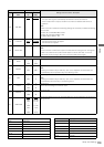
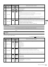
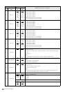
509 PHASE CORR
0000
0001
OFF
ON
Specifies whether or not LTC output from the TIME CODE OUT connector should be phase
controlled.
0: No phase control
1: Phase controlled
510 TCG CF FLAG
0000
0001
OFF
ON
Sets the TCG CF flag.
0: OFF
1: ON
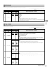
511 DF MODE
0000
0001
DF
NDF
Sets the DF or NDF mode for CTL and TCG.
0: Uses drop frame mode.
1: Uses non-drop frame mode.
NOTE:
This menu is not displayed when 50 is selected in menu No. 25 SYSTEM FREQ.
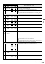
512 TC OUT REF
0000
0001
VOUT
TC_IN
Specifies how the phase is switched for the time code output by the TIME CODE OUT
connector for the external LTC input when the TC INT/EXT switch is set to EXT. (only in EE
mode)
0: Synchronized with output video signal.
1: Synchronized with the external time code input.
513 VITC OUT
0000
0001
SBC
VAUX
Specifies how to output VITC that will be superimposed on the SD output video signal.
0: Outputs the time code recorded in the SBC area as VITC
1: Outputs the time code recorded in the VAUX area as VITC
NOTE:
• VITC data detected in the input video signal is automatically recorded in the VAUX area
during video recording.
•When CMPST and SDI are selected as input signals, VITC, which is output during
recording, outputs a time code that is superimposed on the input signal regardless of
above settings.
514 HD EMBD VITC
0000
0001
OFF
ON
Specifies whether or not VITC data will be superimposed on HD SDI output.
0: Not superimposed
1: Superimposed
Item Setting
Settings and brief function description
FR
No.
SUPER
DISP.
FR
No.
SUPER
DISP.