


26
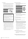
Introduction: Control Reference Guide
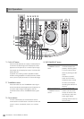
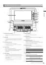
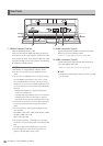
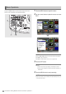
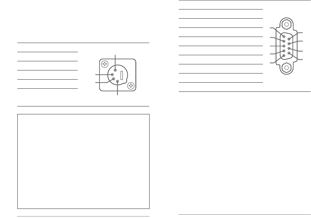
7. DC IN socket
Connect a 12 V DC power supply here. Use an external
12 V DC, 4.3 A (15 A peak or more) DC power supply.
When the voltage goes below approx. 10.6 V, the
power supply of this unit shuts down (when menu No.
180 BATTERY SEL is not “TYPE-A” or “TYPE-B”). The
unit does not automatically recover when the power
comes back on. First turn the POWER switch off, wait a
few seconds before turning the switch back on.
◆ NOTE:
• When using an external DC power supply, be sure to first
turn on the power to the DC power supply and then turn on
the POWER switch on this unit. If the order of the above
procedure is reversed, this unit will malfunction since the
voltage of an external DC power supply rises slowly.
• Inadvertently connecting an input of 18 V or more triggers
an internal protection circuit that shuts down the unit. The
unit will operate normally once the power voltage returns to
normal levels. Be sure not to connect an AC power supply
to this socket.
• When the external DC power supply is connected and set
to on, a minute amount of current will still flow even if the
POWER switch on this unit is set to OFF.
8. Remote control connector
This unit can be connected to an external controller to
enable remote operation of the unit.
RS422A REMOTE(9P)
9. TIME CODE OUT connector
Outputs the playback time code during playback.
Outputs the time code generated by the internal time
code generator during recording.
10.TIME CODE IN connector
Use to record an external time code onto P2 cards.
11.REF VIDEO IN connectors
Input connectors for HD and SD reference video
signals.
◆ NOTE:
• It is recommended that this unit be used with a system that
inputs a reference video signal since video and audio
output signals may otherwise deteriorate.
• Input tri-level sync signals with both positive and negative
polarities as HD reference video signals. Input signals that
meet the input signal and data format.
• Input a black burst signal that complies with SMPTE170M
and ITU624-4 to use for SD reference video signals.
• When no cable is connected to REF VIDEO OUT connector,
the REF VIDEO IN connector is automatically terminated at
75 ohm. Connecting a cable to this connector releases
75. termination.
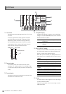
12.AUDIO MONITOR OUT connector
This connector outputs the audio signal (CH1, CH2,
CH3 and CH4) that is selected with the MONITOR
SELECT button.
13.ANALOG COMPOSITE MONITOR OUT connector
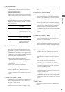
Outputs analog composite monitor video signals.
Pin No. Signal
1Ground
2—
3—
4+12V
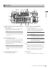
Be sure to check the rating of any external DC power
supply you intend to use to confirm that it is
compatible with this unit. Also check the pin
arrangement of the DC OUT socket of an external DC
power supply with the DC IN socket of this unit to
make sure the polarity is right.
Erroneously applying +12 V to the GND terminal
could cause a fire or lead to injuries.
Connecting a cord with incorrect polarity to the DC IN
connector of another device that is also connected to
this unit could lead to fire or injury.
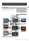
1
2
3
4
Pin No. Signal
1 FRAME GROUND
2 TRANSMIT A
3 RECEIVE B
4 RECEIVE COMMON
5—
6 TRANSMIT COMMON
7 TRANSMIT B
8 RECEIVE A
9 FRAME GROUND
1
2
3
4
5
9
8
7
6