


Introduction: Control Reference Guide
25
Introduction
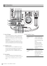
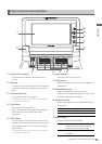
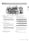
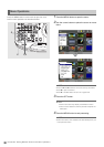
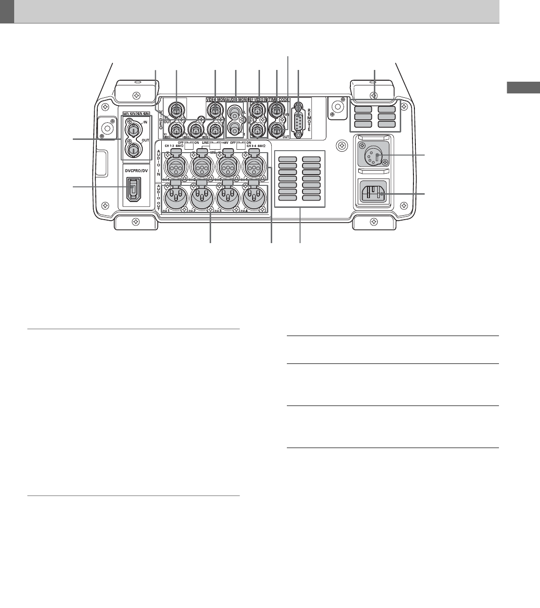
1. SERIAL DIGITAL COMPONENT AUDIO and VIDEO
IN/OUT connectors
These connectors enable input and output of serial
digital component audio and video signals.
◆ NOTE:
• The input digital audio signals must be synchronized with
the video input signals. Otherwise, the audio signals will be
affected by noise.
2. IEEE 1394 digital input/output
This is an IEEE1394 digital interface. It inputs/outputs
IEEE1394 compressed digital signals that comply with
the IEC61883-1, IEC61883-2 and SMPTE396M
standards. Use 6-pin connectors. This connector does
not support bus power.
◆ NOTE:
• AVC-Intra 50 and AVC-Intra 100 (optional) recording and
playback do not support input/output via the IEEE 1394
connector.
3. ANALOG AUDIO OUT connectors
Output analog audio signals.
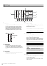
4. ANALOG AUDIO IN connectors/switches
Analog audio input connectors
The input impedance of CH1-2 to CH3-4 can be
switched. The LINE, MIC and 48V switches make it
possible to use CH2 as a microphone input.
5. Fan
Cools this unit. Install the unit making sure that the air
vents are not blocked. If the fan stops due to a
breakdown, “E-10” will appear on the counter display.
While the unit will operate even when the fan has
stopped, it should be shut down immediately.
6. AC IN socket
Connect the supplied power cord to a power outlet.
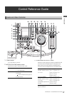
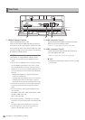
Rear Panel
1
2
345
6
7
8 5
9
101112131415
LINE: Line input for audio input signals from
audio device
MIC: Audio input signal from microphone with
internal power supply (this unit does not
provide phantom microphone power).
+48 V: Audio input signal from microphone with
external power supply (this unit provides
phantom microphone power).