


16
PRV-LX1
En
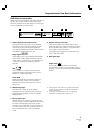
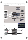
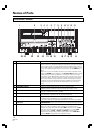
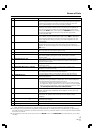
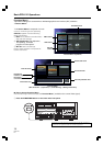
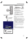
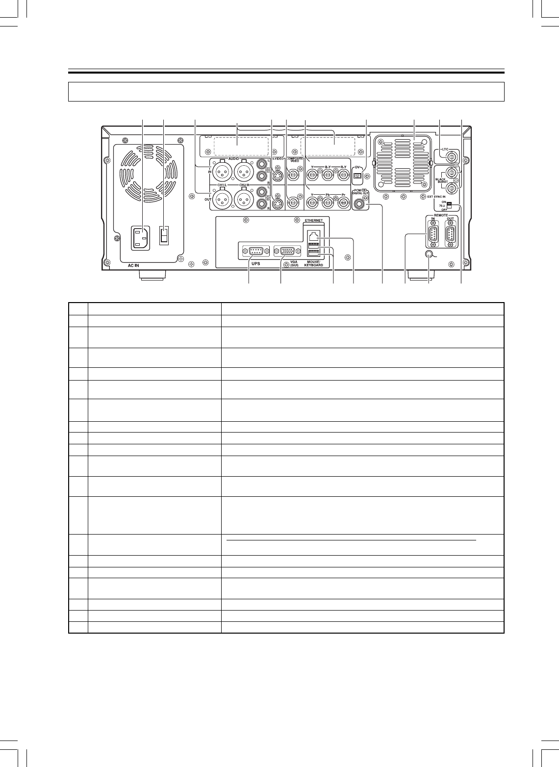
Names of Parts
SIGNAL GND
19
12 3 456 7 8 910
1112131415161718
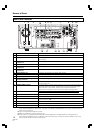
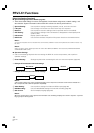
Rear Panel Facilities
*1 Inputs are compatible with signal levels for both BETA and SMPTE (see page 32 for selection methods). However,
since outputs are based on DVD format, they differ from BETA and SMPTE levels. As a result, outputs should be
used only for monitoring.
*2 LTC is not supported in drop frame mode.
*3 SONY is a trademark of Sony Corporation. TR
*4 Functionality is not guaranteed for all possible mouse/keyboards. If unstable operation is experienced, try
reconnecting the USB connector. If operation continues to be erratic, consult your Pioneer dealer or one of the
service centers listed at the end of this manual.
No.
1
2
3
4
5
6
7
8
9
10
11
12
13
14
15
16
17
18
19
Name
AC IN connector
Main power switch
AUDIO CH1/L CH2/R IN/OUT
connectors
S-VIDEO IN/OUT connectors
COMPOSITE VIDEO IN/OUT
connectors
COMPONENT VIDEO IN/OUT
connectors
DV connector (*2)
Fan motor
LTC connector
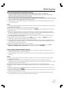
EXT SYNC IN and through
Output connector
Terminate switch
SIGNAL GND terminal
REMOTE IN/OUT connectors
PCM/2 DIGITAL OUT connector
ETHERNET connector
MOUSE/KEYBOARD connectors
VGA (GUI) connector
UPS connector
Expansion slot
Function
Connect to power cord.
When set to ON, the unit enters standby condition and front panel indicator
lights orange.
Input/output connectors for analog audio CH1/L CH2/R signals.
Input/output connectors for S-VIDEO video signal. Output is compatible with S2.
Input/output connectors for analog composite video signals.
Input/output connectors for analog component video signals. (*1)
Connect to DV connector on digital video camera.
Fan motor for cooling internal parts.
Connector for obtaining time code from VHS, VTR, etc.
Use for connecting external sync signal, and for pass-through signals.
Use to terminate sync signal. Set to ON when used alone or when connected
to a terminating unit.
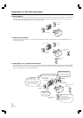
Ground terminal for signals. When using the unit in environments exposed to
high levels of electronic noise, malfunctions may occur to mouse and other
control devices. In such cases, connect a ground wire between the
components to reduce the noise. This is not an electric safety ground.
Connect to external controller when desired for external control of unit.
The
protocol is compatible with SONY format. (*3)
Digital audio output connector.
Use for network connection.
USB connectors for connecting mouse and keyboard, allowing external
control of the unit. (*4)
Connect to VGA monitor for expanded operation.
Connect when using UPS.
Slot for use with expanded function boards.