


97
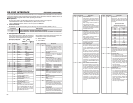
OTHERS
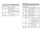
– Warning display –
When an error occurs, BR-DV6000 automatically self-diagnoses the cause and displays an error-
coded warning message on the monitor.
If BR-DV6000 is not in good order, or if an operation error has occurred, an alarm display will be
shown on the monitor or the LCD.
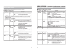
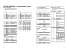
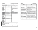
Ⅵ Alarm display (Displayed regardless of the DISPLAY mode)
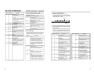
Display Status Action
LOW VOLTAGE
HEAD
CLEANING
REQUIRED!
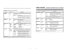
OVER
HEATING!
UNPLUG MAIN
POWER, PLUG
BACK IN
AFTER A
WHILE
The DC power voltage is low.
BR-DV6000 will eventually go into the OPER-
ATE OFF mode if operation is continued.
The video head is dirty. (This message is dis-
played when the DISPLAY mode is ON or
AUTO.) If the head is clogged, it will be detected
and the alarm message will be displayed in the
PLAYBACK mode. When operation is stopped
or when the cassette is ejected, the display will
disappear.
The message will also disappear when the head
cleaning tape is loaded.
The internal temperature of BR-DV6000 has ex-
ceeded the stated value.
This is a system error that occurs when the power
is turned on. The OPERATE indicator on BR-
DV6000 blinks in green. The unit will not accept
any operation commands.
Check the power voltage.
Clean it with a JVC head-clean-
ing tape. (☞ Page 8)
If the message persists despite
cleaning, it could be due to bad
recording condition, defective
tape or head lifespan.
Disconnect the power and place
BR-DV6000 in a cool place. If
this message is displayed
again, the unit may have been
damaged. In such a case, con-
sult your JVC authorized
dealer.
Unplug the power cord from the
power outlet and wait for some
time before plugging it back in.
• For alarm displays resulting from operation errors, Refer to page 24.
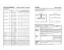
32K CH–1/2
W
ARNING 7001
DRUM MOTOR FAI LURE
03/04/03 STANDBY
-
OFF
11:20:00 TCR 02:00:00:00
32K CH–1/2 SS00inmP0 00 inmP0
HEAD CLEANING REQUIRED!
03/04/03 STANDBY
-
OFF
11:20:00 TCR 02:00:00:00
Warning display Alarm display
96
DATA
0
D1/D2
0000
0101
1010
0000
0101
1010
0000
0101
1010
00
01
10
11
0
1
00
01
10
00000000
00001000
10110000
10111000
––––––––
0
1
0
1
0
1
000
001
010
011
0
1
0
1
00
01
10
0
1
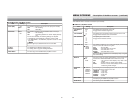
LCD BRIGHTNESS F1 D1 MAX(5)
to
0
to
MIN(–5)
LCD CHROMA F1 D1 MAX(5)
to
0
to
MIN(–5)
LCD CONTRAST F1 D2 MAX(5)
to
0
to
MIN(–5)
LCD AUTO OFF F1 D2 OFF
30MIN
1HOUR
2HOUR
DISPLAY 01 D1 OFF
ON
72 D1 OFF
ON
AUTO
COUNTER POSI. 82 D1 LOWER R
LOWER L
UPPER R
UPPER L
CENTER
TIME CODE 72 D1 OFF
ON
VTR MODE 72 D1 OFF
ON
TAPE REMAIN 82 D2 OFF
ON
TIME/DATE 83 D2 OFF
TIME
DATE
DATE+TM
AUDIO INFO. 72 D1 OFF
ON
EDIT INFO. 72 D1 OFF
ON
DATE STYLE 83 D2 YY/MM/DD
MM/DD/YY
DD/MM/YY
TIME STYLE 83 D2 12H
24H
76543210
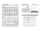
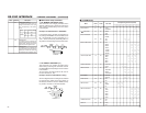
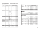
Ⅵ DISPLAY Menus
RS-232C INTERFACE
– RS-232C commands – (continued)
Menu
Corresponding bit values (D1/D2)
Set value