


47
VIDEO
LINE
IN
OUT
MONITOR
OUT
DC12V
DV
IN/OUT
IN OUT
OFF
AUDIO
REMOTE2
IN
B-YR-Y
SYNC IN
TIME CODE
IN OUT
Y
COMPONENT
OUT
CH 1/3 CH 2/4
IN
OUT
MONITOR
OUT
REMOTE1
TIMER
REC PLAY
SERIAL
REMOTE
SINGLE
GND
Y/C
BR-DV6000
PROFESSIONAL
MENU RESET
DISP
SET INDEX+
BLANK CUE UP
HOLD
PHONES REC LEVEL
CH-1/3 CH-2/4
MIC
INDEX–
Mini
CH1/3
NDF
12
H
34
M
34
S
10
F
FREE
CH2/4
STOP
SP222
min
01/02/03
01:23:45 INS
AM
OVER
48k
T
C
L
dB010203040
OVER
W
Y/C
VA
SYNC
r
e
CF
OFF
TIMER
REC PLAY
Ⅵ
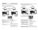
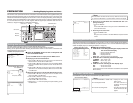
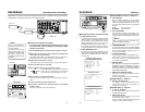
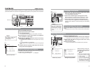
Connect the supplied AC adapter.
To set the power supply to be activated by a timer, plug
the power cord of the AC adapter to the power output
terminal of the timer.
1.
Set the REMOTE/LOCAL switch on the front panel to “LOCAL”.
2.
Select the video or sound to be recorded with the INPUT SE-
LECT switch on the front panel.
With VIDEO INPUT SEL in the VIDEO Menu screen, either the YC
separate signal or the component signal can be selected.
3.
Adjust the recording level of sound.
❈
During DV input, the sound recording level cannot be adjusted.
4.
Load a cassette tape for recording.
5.
Set the TIMER switch on the rear panel to “REC”.
If the DISP button on the front panel is pressed
to change the LCD display to the enlarged
mode, the timer symbol
r
lights up in red.
6.
Set the time, etc., of the external timer.
When the power is supplied to the unit, recording starts automati-
cally.
7.
To stop recording, press the STOP button.
8.
To stop the external timer recording mode, set the TIMER
switch to “OFF”.
The timer symbol
r
of the LCD disappears.
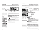
BR-DV6000 can start recording automatically when the power is supplied. Using a commercially
available timer, recording can start at a pre-determined time.
Memo
Use an external timer ex-
clusively to control the start
of VCR operation.
If the power is cut off by an
external timer and the VCR
operation is stopped while
the tape is running, BR-
DV6000 or the tape may be
damaged.
TIMER switch
DC IN terminal
Supplied AC adapter
Timer, etc.
DISP button
LCD display
Timer symbol
RECORDING
– External timer recording –
48
BR-DV6000
PROFESSIONAL
MENU RESET
A.DUB
EJECT
COUNTER
AUDIO INPUT
SELECT
MONITOR OUTPUT REMOTE
LOCAL
CTL L
MIX
R
CH-1/2
MIX
CH-3/4
DV
LINE
Y/C
(CPN)
TC
UB
REW STOP FF
REC
OPERATE
PLAY PAUSE
DISP
SET INDEX+
BLANK CUE UP
HOLD
PHONES REC LEVEL
CH-1/3 CH-2/4
MIC
INDEX–
Mini
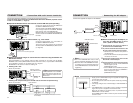
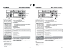
AUDIO MONITOR switch
AUDIO
OUTPUT
switch
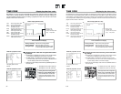
PLAYBACK
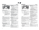
– Setting –
Memo
Output images from the DV terminal are
fixed to the 2nd field images.
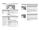
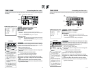
Ⅵ
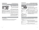
SYSTEM Menu screen (
☞
Page 72)
● SYNC SELECT
This is for setting whether to use the internal
signal or the input video signal as the synchro-
nization signal during playback if there is no in-
put of synchronization signals to the SYNC IN
terminal.
AUTO : Input video signal
EXTERNAL : Internal signal
● STL/F.ADV MODE
This mode is for selecting still images or im-
ages of frame-advance playback. (Field image,
1st field image, 2nd field image and frame im-
age)
● LONG PAUSE TIME
For setting the time (minute) when BR-DV6000
enters the tape protection mode if BR-DV6000
is in the STILL mode for a long time. (5, 3, 2, 1
minute or 30 seconds)
● LONG PAUSE MODE
For selecting the state of BR-DV6000 when it
enters the tape protection mode after it stayed
in the STILL mode for a prolonged period of
time. (F.ADV or STBY-OFF)
● REPEAT MODE
This mode is for turning ON/OFF the REPEAT
PLAYBACK function and selecting the type of
REPEAT PLAYBACK. If REPEAT PLAYBACK
is not performed, set it to OFF. (OFF, INDEX,
VIDEO END, TAPE END)
● PB/DV IN: SYSTEM (2/2) Menu
Set this item according to the signal format of
the tape to be played.
Set here to NTSC for a tape recorded in NTSC.
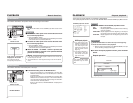
Ⅵ
VIDEO Menu (
☞
Page 79)
● SET UP (for NTSC only)
For selecting whether to enable SET UP for
analog video output signals (composite, Y/C
separate or component).
Ⅵ
AUDIO Menu (
☞
Page 78)
● A. OUT AT SEARCH
For selecting whether sound is output during
variable speed playback.
● AUDIO OUT LEVEL
For selecting the reference level of the audio
output level. (–20dB, –12dB)
Set it to –12dB to playback tapes recorded at
–12dB on a home-use DV machine.
Ⅵ
Setting the switches on the front panel
● AUDIO OUTPUT switch
To play back tapes recorded in the 32kHz mode,
use this switch to select the audio channel for
output signals from the AUDIO OUT terminal,
AUDIO MONITOR OUT terminal or the
PHONES terminal (CH 1/2, CH 3/4, MIX).
In the 48kHz mode, the sound of CH1 and CH2
is output regardless of the setting of this switch.
● AUDIO MONITOR switch
Use this switch to select the audio channel for
output signals from the AUDIO MONITOR OUT
(monaural) or PHONES terminal (L, MIX, R)
(
☞
Page 13)
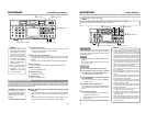
KCABEGAP
EGAPTXEN
FFOEDOMTAEPER
XEDNI.CNUFYEK,
VDA.FEDOMESUAPGNOL
NIM5EMITESUAPGNOL
FFOEMITCERPUKCAB
DN2EDOMVDA.F/LTS
OTUATCELESCNYS
——————]2/1[METSYS———
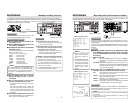
KCABEGAP
FFOTSRUBKCALB
FFO)CSTN(PUTES
C/YLESTUPNIOEDIV
———OEDIV———
KCABEGAP
NOEDAF.V
Bd02–VELTUOOIDUA
ACRLESTUPNIOIDUA
NOHCRAESTUO.A
K84EDOMOIDUA
–––OIDUA–––
SYSTEM (1/2) Menu screen
VIDEO Menu screen
AUDIO Menu screen