


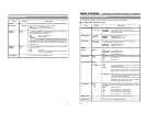

90
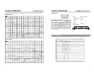
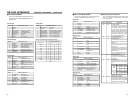
Search speed table (Supported speed only)
32 10
00 00
00 01
00 10
00 11
01 01
01 10
01 11
10 00
10 01
STILL
0.1
0.2
0.3
01 000.5
1
2
5
9 (10)
20
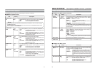
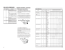
RS-232C INTERFACE
– RS-232C commands – (continued)
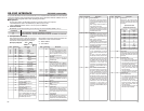
Ⅵ D7: STATUS SENSE
This section describes 5-byte data that are re-
turned when the STATUS SENSE (D7H) com-
mand is sent.
7 Always 1
6 Always 0
5 SHORT FF/REW : In short FF or short REW
4 REC INHIBIT : Recording prohibited
3 CASSETTE OUT :No cassette tape loaded
2 SERO LOCK : Servo locked
1 Undefined : Always 0
0 ERROR :Error occurring
● First byte
7 VIDEO EE :Video output in the EE mode
6 AUD EE : Audio 1 output in the EE mode
5 VIDEO MUTE :Video signals muted
4 AUD MUTE :Audio signals muted
3 WARNING :Problem with the VCR
2 DEW :Condensation in the VCR
1 TAPE BEGIN :Short FF at the tape beginning.
0 TAPE END :Short REW at the tape end
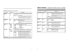
● Second byte
7 TIMER PLAY :TIMER switch set to PLAY
6 TIMER REC :TIMER switch set to REC
5 Unused : Always 0
4 REPEAT :REPEAT PLAYBACK mode ON
3 Unused : Always 0
2 REPEAT MODE : Repeat playback in operation
1 SEARCH MODE :VCR being cueing-up/prerolling
0 Unused : Always 0
● Third byte
7 PLAY MODE :VCR playing
6 FF MODE :VCR fast-forwarding
5 REW MODE :VCR rewinding
4 STOP MODE :VCR stopped
3 STAND BY MODE : VCR on standby
2 EJECT : Cassette tape being ejected
1 REC MODE :VCR recording
0 ADB MODE :VCR audio dubbing
● Fourth byte
7 PAUSE MODE :VCR paused
6 Unused :Always 0
5 SHUTTLE FWD :VCR forward shuttle-searching
4 SHUTTLE REV : VCR reverse shuttle-searching
3 SPEED CODE3 :Refer to the following table.
2 SPEED CODE2 :Refer to the following table.
1 SPEED CODE1 :Refer to the following table.
0 SPEED CODE0 :Refer to the following table.
● Fifth byte
Search speed
Bit No. Status: If the bit is 1
Bit No. Status: If the bit is 1
Bit No. Status: If the bit is 1
Bit No. Status: If the bit is 1
Bit No. Status: If the bit is 1
Speed code (Bit No.)
( ): PAL
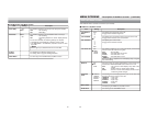
91
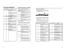
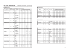
Ⅵ DD: JVC STATUS SENSE
This section describes 4-byte data that are returned
when the STATUS SENSE command is sent.
7 Always 1
6 Always 0
5 Unused :Always 0
4 DMF : Playing back LP-mode tape
3 Unused :Always 0
2 JVC TABLE2 : JVC TABLE 2 enabled
1 JVC TABLE1 : JVC TABLE 1 enabled.
0 LOCAL :REMOTE switch set to LOCAL
ⅷ First byte
7 TC GENERATOR :Time code generator in the TCG
mode.
6 USER BIT : Counter mode set to the UB
mode.
5 TIME CODE :Counter mode set to the TC
mode.
4 CONTROL PULSE :Counter mode set to the CTL
mode.
3 CTL completion :Always 0
2 DROP FRAME :Current time code in the DROP
FRAME mode
1 LTC :Always 1
0 Unused :Always 0
ⅷ Second byte
7 TC REC RUN :TCG set to the Rec Run mode
6 TC REGEN : TCG set to the REGENERATION
mode
5 TC EXTERNAL :TCG set to the EXT mode
4 TC INSERT LED :Time code insert edit mode
3 AUD1 INSERT LED :Audio-1/2 insert edit mode
2 AUD2 INSERT LED :Audio-3/4 insert edit mode
1 VIDEO INSERT LED:Video insert edit mode
0 ASSEM :Assemble mode
ⅷ Third byte
7 TBC PWB IN : Always 1
6 TC PWB IN :Always 1
5 DA3 INSERT LED :Always 0
4 DA4 INSERT LED :Always 0
3 AUTO MODE : Auto editing/Previewing/Review-
ing
2 Unused :Always 0
1 Unused :Always 0
0 Unused :Always 0
ⅷ Fourth byte
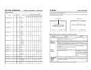
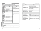
Ⅵ Setup (preset) commands
These commands are for setting various types of VCR
data. The commands corresponding to the settings
can be transmitted.
B
B
B
B
E0
E1
E3
E4
E5
E6
TC DATA PRESET :
For presetting the time code data. To
set, transmit the time data following
this command. Specify the time in or-
der of hour, minute, second and frame,
using two digits for each. When EN-
TER (40h) is transmitted before all dig-
its have been transmitted, the time
code data are specified by entering
digits from the uppermost digit.
TC UB DATA PRESET :
For presetting the user’s bit.
IN DATA PRESET :
For presetting the edit-in point. Set by
transmitting time data following this
command.
Specify the time in order of hour,
minute, second and frame, using two
digits for each.
If ENTER (40h) is transmitted before
all digits have been transmitted, this
command is executed with unspecified
parts set as “0.”
If this is a negative value in the CTL
mode, set 38h to the digit of 10H.
OUT DATA PRESET :
For presetting the edit-out point.
For details, refer to IN DATA PRESET
(E3h) above.
EDIT PRESET :
For selecting the edit mode. Each bit
is defined as shown in the table be-
low.
• ENTER (40h) is invalid.
PREROLL TIME PRESET :
For setting the preroll time. Specify this
by transmitting 2-byte data following
this command. First byte for ten’s place
and second byte for one’s place.
76 4
3210
0011
0 INS ASM Video
3210
0011
0TC
Aud-1 Aud-2
5
First
byte
Second
byte
Bit No. Status: If the bit is 1
Bit No. Status: If the bit is 1
Bit No. Status: If the bit is 1
Bit No. Status: If the bit is 1
Table Command Description