


35
VIDEO
LINE
IN
OUT
MONITOR
OUT
DC12V
DV
IN/OUT
IN OUT
OFF
AUDI O
REMOTE2
IN
B-YR-Y
SYNC IN
TIME CODE
IN OUT
Y
COMPONENT
OUT
CH 1/3 CH 2/4
IN
OUT
MONITOR
OUT
REMOTE1
TIMER
REC PLAY
SERIAL
REMOTE
SINGLE
GND
Y/C
D
V6000
O
NAL
A.DUB
EJECT
COUNTER
AUDIO INPUT
SELECT
MONITOR OUTPUT REMOTE
LOCAL
CTL L
MIX
R
CH-1/2
MIX
CH-3/4
DV
LINE
Y/C
(CPN)
TC
UB
REW STOP FF
REC
OPERATE
PLAY PAUSE
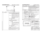
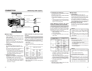
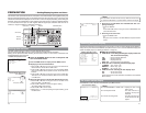
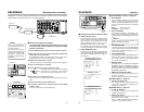
Ⅵ Before connecting the AC adaptor, en-
sure that the TIMER switch is set to
“OFF”. (Refer to “Notes” below.)
1.
Connect the DC cord of the AC adapter to
the DC IN terminal of BR-DV6000.
2.
To prevent accidental disconnection of the
DC cord, fasten the DC cord with a clamp.
1Remove the screw and the clamp shown in
the above figure.
2Insert the DC cord into the clamp and fasten
the clamp unto the unit.
3.
Connect the supplied power cord to the AC
IN terminal of the AC adapter.
4.
Connect the power cord to the power outlet.
• BR-DV6000 is turned on and the OPERATE
indicator lights up in red.
(OPERATE OFF mode)
• If DC IN MODE of the SYSTEM (2/2) Menu
screen is set to “OPE ON”, the OPERATE in-
dicator will light up in green.
(OPERATE ON mode)
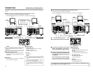
Memo
●
Even in the OPERATE OFF mode, a small
amount of electricity will still flow into the unit.
●
When the unit is in the OPERATE OFF mode,
no operation can be performed except that
of the OPERATE buttons and cassette load-
ing/ejecting.
Notes
• Supply power to BR-DV6000 using the supplied AC adapter. Do
not use other power sources.
• Do not unplug the DC cord and/or the power cord during recording
or playback.
• If the supply voltage is low, an alarm display of “LOW VOLTAGE” is
shown.
• If the TIMER switch is set to REC or PLAY, recording or playback
begins when power is supplied to the DC IN terminal.
When the AC adapter is connected, ensure in particular that the
TIMER switch is not set to REC.
Set the TIMER switch to REC or PLAY only when an external timer
function is used.
LOW VOLTAGE
Alarm message
Supplied power
cord
Supplied AC adaptor
Screw
Clamp
DC cord
DC IN
terminal
TIMER switch
OPERATE indicator
OPERATE button
CONNECTION
– Connecting the AC adapter –
Connect the supplied AC adaptor to BR-DV6000.
34
VIDEO
LINE
IN
OUT
MONITOR
OUT
DC12V
DV
IN/OUT
IN OUT
OFF
AUDIO
REMOTE2
IN
B-YR-Y
SYNC IN
TIME CODE
IN OUT
Y
COMPONENT
OUT
CH 1/3 CH 2/4
IN
OUT
MONITOR
OUT
REMOTE1
TIMER
REC PLAY
SERIAL
REMOTE
SINGLE
GND
Y/C
SERIAL OUT
VIDEO
LINE
IN
OUT
MONITOR
OUT
DC12V
DV
IN/OUT
IN OUT
OFF
AUDIO
REMOTE2
IN
B-YR-Y
SYNC IN
TIME CODE
IN OUT
Y
COMPONENT
OUT
CH 1/3 CH 2/4
IN
OUT
MONITOR
OUT
REMOTE1
TIMER
REC PLAY
SERIAL
REMOTE
SINGLE
GND
Y/C
IN OUT IN
SERIAL
SERIAL OUT
SERIAL
DV: BR-DV6000
❈
VIDEO
LINE
IN
OUT
MONITOR
OUT
DC12V
DV
IN/OUT
IN OUT
OFF
AUDIO
REMOTE2
IN
B-YR-Y
SYNC IN
TIME CODE
IN OUT
Y
COMPONENT
OUT
CH 1/3 CH 2/4
IN
OUT
MONITOR
OUT
REMOTE1
TIMER
REC PLAY
SERIAL
REMOTE
SINGLE
GND
Y/C
SERIAL IN
SERIAL OUT
RM-G30
VIDEO
LINE
IN
OUT
MONITOR
OUT
DC12V
DV
IN/OUT
IN OUT
OFF
AUDI O
REMOTE2
IN
B-YR-Y
SYNC IN
TIME CODE
IN OUT
Y
COMPONENT
OUT
CH 1/3 CH 2/4
IN
OUT
MONITOR
OUT
REMOTE1
TIMER
REC PLAY
SERIAL
REMOTE
SINGLE
GND
Y/C
SERIAL IN
SERIAL OUT
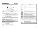
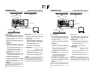
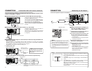
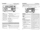
The following describes examples of serial remote terminal connection.
To use the serial remote terminals, set REMOTE SEL SER of the REMOTE (1/2) Menu screen
to “ON” or “LOC+REM.” (
☞
Page 75)
Connect the wired remote controller RM-G30 to
the SERIAL REMOTE IN terminal.
The commands of the SERIAL REMOTE IN termi-
nal is through-output from the SERIAL REMOTE
OUT terminal. (Only with OPERATE ON)
Multiple VCRs can be operated with RM-G30 by
series connection of the SERIAL REMOTE IN/OUT
terminals.
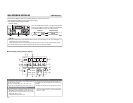
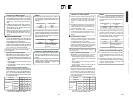
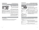
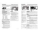
Ⅵ Start/stop recording with an external switch, e.g., a foot switch.
Connect an external switch, e.g., a foot switch, to
the SERIAL REMOTE IN terminal.
The format of the input signals can be selected
with FOOT SW in the REMOTE (2/2) Menu screen.
(
☞
Page 46)
Ⅵ Dubbing of playback images or sound with other machines using the SERIAL RE-
MOTE OUT terminal.
When BR-DV6000 is in the playback mode, the REC command can be output from the SERIAL
REMOTE OUT terminal (REPLICATION function). With this function, a tape loaded in BR-DV6000
can be dubbed on another unit. For details, refer to
☞
Page 57.
BR-DV6000 can be used as a master or dubbing unit.
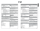
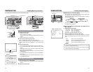
● Dubbing with 1 VCR.
Ⅵ
Operate BR-DV6000 with the wired remote controller RM-G30 (sold separately)
●
Dubbing with multiple VCRs (Up to 50 VCRs can be controlled comprehensively.)
Memo
If REPLICATION of the SYSTEM
(2/2) Menu screen is set to DV, the
REC command is output from the
DV terminal.
Through-output
Through-output
Foot
switch
(Master unit) BR-DV6000
(Dubbing unit) VCR
with a SERIAL terminal
Video
Sound
Dubbing unit: VCR with SERIAL IN and OUT terminals
SERIAL
terminal
REC command
Signal distributor
CONNECTION
– Connection with serial remote terminals –
(Master unit) BR-DV6000
Video
Sound