


19
¤
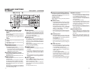
[SERIAL REMOTE OUT] terminal
(mini jack)
• This terminal is for direct through-output of
serial commands of the serial remote input
terminal. (Only with OPERATE ON)
• If REPLICATION of the SYSTEM (2/2) Menu
screen is set to SERIAL, this terminal out-
puts REC commands when BR-DV6000 be-
gins playback. (REPLICATION mode)Use this
function to connect BR-DV6000 to a dubbing
device for dubbing its playback video or play-
back sound.
‹
[REMOTE 1] RS-422A terminal
(D-SUB 9-PIN)
This terminal is for connecting to an RS-422A
serial interface-compatible editing remote con-
troller (e.g. RM-G820).
With this terminal, BR-DV6000 can be used as
a player or recorder of an editing system.
To operate BR-DV6000 with RS-422A, perform
the following settings.
• Set REMOTE SEL 9-PIN in the REMOTE (1/
2) Menu screen to “ON”.
• Set the
4
REMOTE / LOCAL switch on the
front panel to “REMOTE”.
Memo
●
Use screws, of the inch, not metric, system,
for fastening the connectors.
●
This part can be replaced by the RS-232C
serial interface board SA-K46U (sold sepa-
rately).
Consult your JVC authorized service agent
for such replacements.
›
[REMOTE 2] JVC Bus terminal
(12-PIN)
This terminal is for connecting to the JVC bus
interface-compatible editing remote controller
(RM-G800, RM-G805).
With this terminal, BR-DV6000 can be used as
a player or recorder of an editing system.
To operate BR-DV6000 with this terminal, per-
form the following settings.
• Set REMOTE SEL JVC in the REMOTE (1/
2) Menu screen to “ON”.
• Set the
4
REMOTE / LOCAL switch on the
front panel to “REMOTE”.
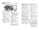
fi
Slot cover for an optional board
This cover can be removed to install any of the
following optional boards.
• SA-DV6000 network board
• SA-X61 AUDIO XLR IN board (2ch)
• SA-X62 AUDIO XLR OUT board (2ch)
Memo
● With the SA-X61U AUDIO XLR IN board in-
stalled, whether sound signals are input to
the XLR IN terminal or the AUDIO IN termi-
nal can be selected with AUDIO INPUT SEL
in the AUDIO MENU. If the MIC terminal is in
use, the MIC terminal precedes.
● With the SA-X62U AUDIO XLR OUT board
installed, the audio channel to which signals
are output can be selected with the AUDIO
OUTPUT switch.
18
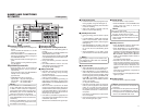
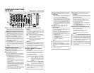
^
DC power input terminal (2-PIN)
This terminal is for inputting DC 12 V. Connect
the DC power cord of the supplied AC adapter.
&
[SIGNAL GND] terminal
This is the grounding terminal for signals.
*
DC power cord clamp
Use this clamp to fasten the DC power cord.
(
[DV IN/OUT] terminal
This is the input/output terminal for IEEE1394-
compliant digital signals. It is for connecting to
video equipment with a DV terminal.
• To enable signal input via this terminal, set
the INPUT SELECT switch located on the
front panel to “DV”.
• Signals that come from this terminal are out-
put regardless of the setting of the INPUT
SELECT switch.
• If REPLICATION of the SYSTEM (2/2) Menu
is set to DV, the REC command is output from
this terminal when BR-DV6000 begins play-
back. (REPLICATION mode)
• Set PB/DV IN in the SYSTEM(2/2) Menu
screen according to the signal format to be
input to this terminal. (NTSC or PAL)
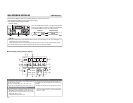
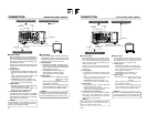
NAMES AND FUNCTIONS
OF PARTS
– Rear panel – (continued)
Memo
●
When power is supplied to this terminal, the
OPERATE indicator located on the front panel
lights up. (The indicator turns red when BR-
DV6000 is in the OPERATE OFF state)
●
Whether to set BR-DV6000 to enter the OP-
ERATE ON mode or OPERATE OFF mode
when power is supplied to the terminal can
be selected with DC IN MODE in the SYS-
TEM (2/2) Menu screen.
●
If the
)
TIMER switch on the rear panel is
set to “REC” or “PLAY”, recording or playback
will be automatically started when power is
supplied to the terminal. (Timer recording/
playback)
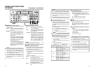
)
[TIMER] recording/playback
switch
This switch is for setting BR-DV6000 to start
timer recording or timer playback when power
is supplied to the
^
DC power input terminal
according to an external timer.
OFF : No timer recording or timer playback.
REC : When power is supplied, BR-DV6000
starts recording automatically.
(Timer recording)
PLAY : When power is supplied, BR-DV6000
starts playback automatically.
(Timer playback)
Memo
● To use this terminal as the foot switch input,
set FOOT SW in the REMOTE (2/2) Menu
screen. (
☞
Page 77)
VIDEO
LINE
IN
OUT
MONITOR
OUT
DC12V
DV
IN/OUT
IN OUT
OFF
AUDIO
REMOTE2
IN
B-YR-Y
SYNC IN
TIME CODE
IN OUT
Y
COMPONENT
OUT
CH 1/3 CH 2/4
IN
OUT
MONITOR
OUT
REMOTE1
TIMER
REC PLAY
SERIAL
REMOTE
SINGLE
GND
Y/C
&
fi
*
^
(
⁄
¤
)‹
›
Memo
● If the TIMER switch is set to “REC” or “PLAY”,
BR-DV6000 automatically enters the OPER-
ATE ON mode upon DC power on even when
DC IN MODE in the SYSTEM (2/2) Menu
screen is set to “OPE OFF”.
⁄
[SERIAL REMOTE IN] terminal
(mini jack)
This terminal is for connecting to the serial re-
mote controller RM-G30 (sold separately).
To operate BR-DV6000 with this terminal, per-
form the following settings.
• Set REMOTE SEL SER in the REMOTE
(1/2) Menu screen to “ON” or “LOC+REM.”
ON : When the
4
REMOTE / LOCAL
switch on the front panel is set to
“REMOTE”, this terminal becomes
effective.
LOC+REM: This terminal is effective regardless
of the setting of the
4
REMOTE /
LOCAL switch on the front panel.