


E
U
27
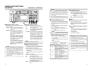
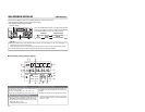
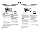
4 Drop/Non-drop display (for NTSC only)
Displays the framing mode of the time code.
NDF : Non-drop frame
DF : Drop frame
PAL : Displays when PB/DV IN in the SYSTEM (2/2)
Menu screen is set to PAL.
5 Time code mode display
Displays the time code mode set in the TC/UB/CLOCK
Menu screen.
REGN : Regeneration mode
RRUN : REC RUN preset mode
FREE : FREE RUN preset mode
EXT : This is displayed when time codes are input to
the TIME CODE IN terminal (with TCG
SOURCE set to EXTERNAL).
It blinks when no time code is input or when the
phase of an external time code is not locked
with the phase of the video signal.
DUPL : This is displayed when TC DUPLICATE is set
to AUTO or NON DROP.
(Enter the time code of the DV terminal.)
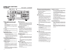
6 Counter mode
The counter mode selected with the COUNTER switch
on the front panel is displayed.
C
T
L
: CTL counter
T
C
: Time code
U
B
: User’s bit
7 Counter display
• The CTL counter is displayed as a 7-digit number with + or –.
The time code/user’s bit is displayed as an 8-digit number.
8 VCR mode display
Displays the operation mode of the VCR.
The reservation of mode is displayed in blinking light.
NOCAS (no cassette tape), EJECT, STBON (standby-
on), STBOF (standby-off), PLAY, STILL, FF, REW, SHTL,
ADUBP (audio dubbing pause), REC, RECP (recording
pause), EDIT, POFF (operate off)
9 VCR mode graphic display
c
: Eject
L
: Stop
:
: Play
J
: Still
Z
: FF/Forward search
+
: REW/ Reverse search:
a
: Record
aJ
: Recording pause
: Audio dubbing
J
:Audio dubbing pause
0 Tape symbol display
: This symbol is displayed when a cassette tape is
loaded.
It blinks during loading or ejecting of a cassette
tape.
If the rear switch of the cassette tape is set to
SAVE, it is displayed in yellow.
! Remaining tape time display
Displays the remaining time (minutes). Blinks if the re-
maining time is less than 4 minutes.
When the remaining time is being confirmed, “– ––” is
displayed. SP will not be displayed when a DVCAM cas-
sette tape is being played back.
@ Time/Date display
The data of the b
uilt-in clock will be displayed during re-
cording or in the ST
OP mode. Displays the data of the
tape during playback.
If the date/time is not set up
, “–– –” is displayed.
#Input video signal display
Displays the input video signal selected with the INPUT
SELECT switch on the front panel.
Blinks if the selected signal is not input (LINE, Y/C, CPNT,
or DV).
(
LINE
,
Y/C
,
CPNT
,
DV
)
In the case of a copy-prohibiting signal, it will be dis-
played in yellow.
SYNC
: It is displayed when signals are input via the SYNC
IN terminal with EXTERNAL SYNC selected.
$ Editing mode display
The editing mode selected with the editing remote con-
troller is displayed.
(ASSEM, INSV, INSA, INSVA, INS TC, INS VA12, INS
VA34, INS A12, INS A34)
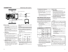
% Timer display
r
: It is displayed when the TIMER switch on the rear
panel is set to REC or PLAY.
REC: RED PLAY: GREEN
^ Wide screen ID signal display
W
: It will be displayed when a wide screen ID signal
exists in the input signal of the Y/C or DV terminal.
The data on the tape is displayed during playback.
& Condensation display
: It is displayed when condensation occurs.
* Option display
It is displayed when an option board is connected.
XLI
: SA-X61 connection
XLO
: SA-X62 connection
e
: SA-DV6000 connection
E-27
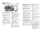
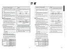
4 Drop/Non-drop display (for NTSC only) /NTSC mode
Displays the framing mode of the time code.
NDF : Non-drop frame (NTSC only)
DF : Drop frame (NTSC only)
NTSC : Displays when PB/DV IN in the SYSTEM (2/2)
Menu screen is set to NTSC.
5 Time code mode display
Displays the time code mode set in the
TC/UB/CLOCK
Menu screen.
REGN : Regeneration mode
RRUN : REC RUN preset mode
FREE : FREE RUN preset mode
EXT : This is displayed when time codes are input to
the TIME CODE IN terminal (with TCG
SOURCE set to EXTERNAL).
It blinks when no time code is input or when the
phase of an external time code is not locked
with the phase of the video signal.
DUPL : This is displayed when TC DUPLICATE is set
to AUTO.
(Enter the time code of the DV terminal.)
6 Counter mode
The counter mode selected with the COUNTER s
witch
on the front panel is displa
yed.
C
T
L
: CTL counter
T
C
: Time code
U
B
: User’s bit
7 Counter display
• The CTL counter is displa
yed as a 7-digit number with + or –.
The time code/user
’s bit is displayed as an 8-digit number.
• With NTSC, the character/symbol at the end varies depending
on the time code framing mode.
F : Non-drop frame.
.(dot): Drop frame.
With PAL, this is fixed to F.
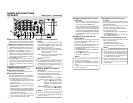
8 VCR mode display
Displays the operation mode of the
VCR.
The reservation of mode is displayed in blinking light.
NOCAS (no cassette tape), EJECT, STBON (standby-
on), STBOF (standby-off), PLAY, STILL, FF, REW, SHTL,
ADUBP (audio dubbing pause), REC, RECP (recording
pause), INSERT, ASSEM, OPOFF (operate off)
9 VCR mode graphic display
c
: Eject
L
: Stop
:
: Play
J
: Still
Z
: FF/Forward search
+
: REW/ Reverse search:
a
: Record
aJ
: Recording pause
:Audio dubbing
J
: Audio dubbing pause
0 Tape symbol displa
y
: This symbol is displayed when a cassette tape is
loaded.
It blinks during loading or ejecting of a cassette
tape.
If the rear switch of the cassette tape is set to
SAVE, it is displayed in yellow.
! Remaining tape time displa
y
Displays the remaining time (min
utes). Blinks if the re-
maining time is less than 4 minutes.
When the remaining time is being confirmed,
“– ––” is
displayed. SP will not be displayed when a DVCAM cas-
sette tape is being played back.
@ Time/Date displa
y
The data of the b
uilt-in clock will be displayed during re-
cording or in the ST
OP mode. Displays the data of the
tape during playback.
If the date/time is not set up,
“– ––” is displayed.
# Input video signal display
Displays the input video signal selected with the INPUT
SELECT switch on the front panel.
Blinks if the selected signal is not input (LINE,
Y/C, CPNT,
or DV).
(
LINE
,
Y/C
,
CPNT
,
DV
)
In the case of a cop
y-prohibiting signal, it will be dis-
played in yellow.
SYNC
: It is displayed when signals are input via the SYNC
IN terminal with EXTERNAL SYNC selected.
$ Editing mode display
The editing mode selected with the editing remote con-
troller is displayed.
(ASSEM, INSV, INSA, INSVA, INS TC, INS VA12, INS
VA34, INS A12, INS A34)
% Timer display
r
: It is displayed when the TIMER switch on the rear
panel is set to REC or PLAY.
REC: RED PLAY: GREEN
^ Wide screen ID signal display
W
: It will be displayed when a wide screen ID signal
exists in the input signal of the Y/C or DV terminal.
The data on the tape is displayed during playback.
& Condensation displa
y
: It is displayed when condensation occurs.
* Option display
It is displayed when an option board is connected.
XLI
: SA-X61U connection
XLO
: SA-X62U connection
e
: SA-DV6000 connection