


93
DATA
0
D1/D2
11
01
0
1
0
1
01
10
000
001
010
011
100
101
110
010
011
100
101
111
00
10
000
001
010
100
00
01
0
1
00
01
10
000
001
010
011
100
101
0
1
0
1
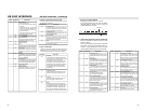
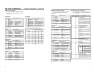
SYNC SELECT 01 D2 AUTO
EXTERNAL
95 D1 INDEX
VAR
STL/F.ADV MODE 93 D1 FIELD
FRAME
95 D2 1ST
2ND
BACK UP REC TIME
95 D1 OFF
25MIN
55MIN
75MIN
115MIN
175MIN
265MIN
LONG PAUSE TIME 10 D1 30SEC
1MIN
2MIN
3MIN
5MIN
LONG PAUSE MODE
10 D1 STBY-OFF
F.ADV
REPEAT MODE 01 D2 OFF
TAPE END
INDEX
VIDEO END
DC IN MODE 95 D1 OPE OFF
OPE ON
INDEX WRITE 88 D2 OFF
ON
REPLICATION 95 D1 OFF
SERIAL
DV
REPLICATE DELAY 95 D2 OFF
1SEC
2SEC
3SEC
4SEC
5SEC
OPERATION LOCK 01 D1 OFF
ON
PB/DV IN 08 D2 NTSC
PAL
76543210
, ”KEY FUNC.
“
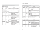
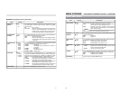
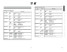
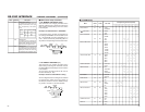
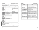
Ⅵ SYSTEM Menus
Menu
Corresponding bit values (D1/D2)
Set value
92
RXD
0AH
EDH
0AH
01H
0AH
D1
7654321
01EXTERNAL :
0
D2
DATA0
0AH
D2
TXD
RXD
01HD3H
0AH
D1
7654321
1 1
0 1
AUTO :
EXTERNAL :
0
D2
D2
TXD
DATA0
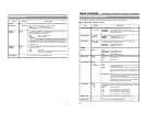
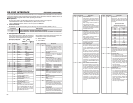
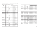
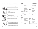
RS-232C INTERFACE
– RS-232C commands – (continued)
E7
8E
8F
TIMER MODE SELECT :
For selecting the counter mode. Fol-
lowing this command, send 1-byte
data corresponding to the counter
mode.
DATA SELECT :
For setting the date. Following this
command, send 6-byte numeric data.
Specify month, date and year (in this
sequence) with two digits for each.
TIME SELECT :
For setting the time. Following this
command, send 6-byte numeric data.
Specify hour, minute and second (in
this sequence) with two digits for each.
1
2
5
TC
CTL
UB
Low
High
Counter mode
3
(Fixed)
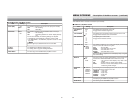
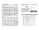
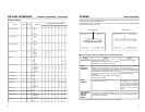
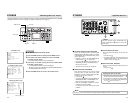
Ⅵ Menu switch setup command
● ED: MEMORY SW PRESET (B/J1)
This command is for changing the VCR’s menu
switches. Following this command, transmit the
data (3 bytes) corresponding to the menu switch
to be changed.
Example: Set SYNC SELECT to EXTERNAL.
In the diagram below, the data corresponding to
the setting of EXTERNAL show that DATA 0, D2
No. 1 bit and D2 No. 0 bit are, respectively, 01, 0
and 1. Set the command by transmitting data in a
way that the corresponding bit values match them.
Bit No.
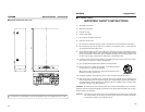
● D3: MEMORY SW SENSE (J1)
This command is for checking the VCR’s menu
switch setting. Following this command, transmit
the data (DATA0) corresponding to the menu switch
to be checked.
You can confirm the setting with the bit count of
the returned data (D1, D2).
Example: Check the SYNC SELECT setting.
As in the diagram below, the setting can be checked
by confirming the values for the menu switch. In
this example, check the values for DATA0 (namely
01), D2 No. 1 and No. 0 of the returned data.
Bit No.
Table Command Description