


16
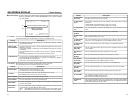
NAMES AND FUNCTIONS
OF PARTS
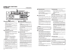
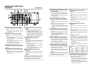
– Rear panel –
1
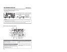
[VIDEO LINE IN] terminal (BNC)
This is the input terminal for composite video
signals.
• To input video via this terminal, set the IN-
PUT SELECT switch located on the front
panel to “LINE”.
2
[VIDEO Y/C IN] terminal (4-PIN)
This is the input terminal for YC separate video
signals.
• To input video via this terminal, the following
settings are required.
Set VIDEO INPUT SEL in the VIDEO Menu
screen to “Y/C”.
Set the INPUT SELECT switch located on
the front panel to “Y/C (CPN)”.
• When wide-screen ID signals are input, the
wide-screen ID signal is recorded.
3
[VIDEO LINE OUT] terminal (BNC)
This is the output terminal for composite video
signals.
4
[VIDEO Y/C OUT] terminal (4-PIN)
This is the output terminal for Y/C separate video
signals.
• When tapes that have recorded wide-screen
signals are played back, the wide-screen ID
signal is output.
5
[VIDEO MONITOR OUT] terminal
(BNC)
This terminal is for connecting to a monitor-TV.
• It outputs composite video signals.
• It displays the Menu setting screen, Date/
Time setting screen and warning information.
• If DISPLAY in the DISPLAY Menu screen is
set to “ON” or “AUTO”, information will be dis-
played on-screen, e.g., the operation mode,
date/time and counter. (
☞
Page 20)
6 [COMPONENT IN] terminal
(BNCן3)
This is the input terminal for component video
signals (Y/R-Y/B-Y). The signal level is high (ß
cam spec).
• To input video of this terminal, the following
settings are required.
Set VIDEO INPUT SEL in the VIDEO Menu
screen to COMPONENT.
Set the INPUT SELECT switch located on
the front panel to “Y/C (CPN)”.
7
[COMPONENT OUT] terminal
(BNCן3)
This is the output terminal for component video
signals (Y/R-Y/B-Y). The signal level is high (ß
cam spec).
Memo
Whether or not to enable SET UP for analog
signals (composite, YC separate and compo-
nent signals) can be selected with SET UP in
the VIDEO Menu screen (for NTSC only).
VIDEO
LINE
IN
OUT
MONITOR
OUT
DC12V
DV
IN/OUT
IN OUT
OFF
AUDIO
REMOTE2
IN
B-YR-Y
SYNC IN
TIME CODE
IN OUT
Y
COMPONENT
OUT
CH 1/3 CH 2/4
IN
OUT
MONITOR
OUT
REMOTE1
TIMER
REC PLAY
SERIAL
REMOTE
SINGLE
GND
Y/C
2
1
6
7
!
@
4
$
3
5809#%
17
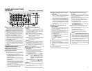
8
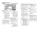
[SYNC IN] synchronization input
terminal (BNC)
This is the terminal for inputting reference syn-
chronization signals from an external source.
For external synchronization signals, input com-
posite video signals of 1V (p-p) or lower (e.g.,
black burst signal).
(
☞
Page 29 “Synchronization signal”)
9
[TIME CODE IN] terminal (BNC)
This is the SMPTE-compliant time code input
terminal.
It is for connecting to an external time code gen-
erator.
For external time code signals, use those that
synchronize with the video signals.
• To input external time codes, set TCG
SOURCE of the TIME CODE Menu to “EX-
TERNAL”.
0
[TIME CODE OUT] terminal (BNC)
This is the SMPTE-compliant time code output
terminal.
It outputs time codes recorded on the tape dur-
ing playback and data generated by the time
code generator during recording.
With the COUNTER switch set to CTL, time
code is not output.
!
[CH1/3 AUDIO IN] terminal (RCA)
Use this terminal to input analog audio signals.
To enable audio input via this terminal, set the
INPUT SELECT switch located on the front
panel to “LINE” or “Y/C (CPN)”.
Usually, analog signals are recorded on CH1.
For audio dubbing, they are recorded on CH3.
@
[CH2/4 AUDIO IN] terminal (RCA)
Use this terminal to input analog audio signals.
To enable audio input via this terminal, set the
INPUT SELECT switch located on the front
panel to “LINE” or “Y/C (CPN)”.
Usually, analog signals are recorded on CH2.
For audio dubbing, they are recorded on CH4.
#
[CH1/3 AUDIO OUT] terminal
(RCA)
Use this terminal to output analog audio sig-
nals.
In the 48k audio mode, it outputs the sound of
CH1.
When audio dubbing is paused, it outputs the
sound of CH3.
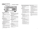
In the 32k audio mode, the sound is selected
with the AUDIO OUTPUT switch located on the
front panel.
(Refer to the table below.)
$
[CH2/4 AUDIO OUT] terminal
(RCA)
Use this terminal to output analog audio sig-
nals.
In the 48k audio mode, it outputs the sound of
CH2.
When audio dubbing is paused, it outputs the
sound of CH4.
In the 32k audio mode, the sound is selected
with the AUDIO OUTPUT switch on the front
panel.
(Refer to the table below.)
Memo
If the AUDIO IN terminal and the MIC terminal
located on the front panel are used simulta-
neously, the MIC terminal will precede.
Memo
In the following modes, the channel that receives
output signals from the AUDIO OUT terminal
can be selected with the AUDIO OUTPUT
switch.
• During playback of tapes recorded in the 32k
audio mode
• During audio dubbing
• In the EE mode for DV input in the 32k audio
mode
%
[AUDIO MONITOR] terminal (RCA)
This terminal is for connecting to a monitor TV
and monitors the sound from its speakers.
Monaural sounds are output.
• The audio channel to be monitored can be
selected with the AUDIO MONITOR switch
located on the front panel.
For audio channels that receive output sig-
nals from this terminal in the 32k audio mode,
refer to the table in page 13.
AUDIO OUTPUT
switch
AUDIO OUT terminal
CH1/3 CH2/4
CH1/2 CH1 CH2
MIX CH1, 3 mix CH2, 4 mix
CH3/4 CH3 CH4