


31
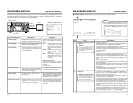
● Connecting to a monitor TV
A monitor TV can be connected to the AUDIO
MONITOR OUT terminal.
The sound output from the AUDIO MONITOR
OUT terminal is monaural.
• The volume is adjusted through the monitor
TV.
• The output channel can be selected with the
AUDIO MONITOR switch on the front panel
(Refer to the following table).
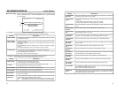
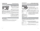
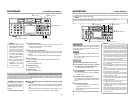
AUDIO MONITOR switches and output
channels of AUDIO OUTPUT/PHONES
In the following cases, the output channels from
the AUDIO MONITOR OUTPUT/PHONES termi-
nal vary according to the setting of the AUDIO
MONITOR switch and the AUDIO OUTPUT switch.
The table below shows the channels.
• During playback of tapes recorded in the
32kHz audio mode.
• During audio dubbing.
• In the EE mode of DV input in the 32 kHz
audio mode.
• In the 48kHz audio mode or during normal
recording, it outputs to CH1/2 channel (the
OUTPUT switch listed in the above table
shows the setting of CH1/2).
• When audio dubbing is paused, it outputs to
CH3/4 channel (the OUTPUT switch listed in
the above table shows the setting of CH3/4).
• When MIX is selected, the PHONES termi-
nal outputs stereo sound.
● Digital output
IEEE1394-compliant digital signals are output
from the DV IN/OUT terminal.
Ⅵ Input signal
● Analog signal
CH 1/3 AUDIO IN terminal. (RCAן2)
There are analog input terminals for 2 chan-
nels. Recording cannot be performed to 4 chan-
nels at the same time. Sound from each termi-
nal is usually recorded to CH1 and CH2.
To record to CH 3 and CH 4, set AUDIO MODE
of the AUDIO Menu screen to 32 k and record
it in the audio-dubbing mode. (
☞
Page 44)
● Microphone input terminal
This terminal is for connecting to a monaural
microphone. The same sound is recorded on
the 2 channels.
Memo
● To record sound on the AUDIO IN terminal
and MIC terminal, set the INPUT SELECT
switch on the front panel to “LINE” or “Y/C
(CPN)”.
● If the [AUDIO IN] terminal and [MIC] terminal
are used at the same time, the [MIC] termi-
nal precedes.
● Digital input
IEEE1394-compliant digital signals are input
into the DV IN/OUT terminal.
• To enable audio input into this terminal, set
the INPUT SELECT switch to DV.
• The AUDIO MODE (48 K or 32 K) will be one
of input signals.
• During digital signal input, the recording level
cannot be adjusted.
Memo
● An input/output board (sold separately) of the
XLR connector can be installed in the optional
slot.
SA-X61 AUDIO XLR IN board
SA-X62 AUDIO XLR OUT board
These boards cannot be installed at the same
time.
● For BR-DV600 player, when the mode is
changed from STILL to PLAY, sound will be
muted for a while shortly after the audio out-
put. Thereafter, it will resume as per normal.
(This does not occur with BR-DV600A.)
AUDIO switch MONITOR OUT/
PHONES terminal
MONITOR
L
MIX
R
OUTPUT
CH1/2
MIX
CH3/4
CH1/2
MIX
CH3/4
CH1/2
MIX
CH3/4
CH1
CH1/3
CH3
CH1/2
CH1/2/3/4
CH3/4
CH2
CH2/4
CH4
30
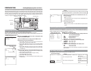
VIDEO
LINE
IN
OUT
MONITOR
OUT
DC12V
DV
IN/OUT
IN OUT
OFF
AUDIO
REMOTE2
IN
B-YR-Y
SYNC IN
TIME CODE
IN OUT
Y
COMPONENT
OUT
CH 1/3 CH 2/4
IN
OUT
MONITOR
OUT
REMOTE1
TIMER
REC PLAY
SERIAL
REMOTE
SINGLE
GND
Y/C
DV
DV
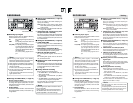
AUDIO
OUTPUT
switch
CH1/2
CH3/4
MIX
CH1
CH3
CH1/3
CH2
CH4
CH2/4
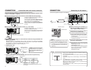
AUDIO OUT terminal
CH1/3
(L)
CH2/4
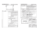
(R)
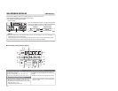
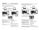
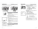
CONNECTION
– Connecting audio signals –
Audio output of VCR
Input
Audio input of VCR
Analog audio
Slot cover for optional board
(2 channels)
Monaural
Microphone
Stereo
Headphone
MONITOR OUT analog (monaural)
Monitor
Output
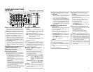
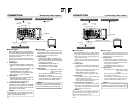
Ⅵ Output signal
When BR-DV6000 is in the STOP, REC or EDIT
mode, signals (EE sound), which have been
input, are output.
During the PLAYBACK mode (including the
playback of the pre-roll part during editing), the
playback sound is output.
However, in the edit mode with analog input,
signals cannot be output to the DV OUT termi-
nal properly.
●
Analog signal
CH 1/3, CH 2/4 AUDIO terminal (RCAן2).
There are analog audio terminals for 2 chan-
nels.
For the DV format, tracks are available for 4
channels (in the 32kHz audio mode).
• In the 32kHz mode, from which one of the 4
channels sound is output can be selected with
the AUDIO OUTPUT switch on the front
panel. (Refer to the table on the right.)
● Headphone terminal
Sound can be checked in stereo using a
headphone. The volume can be adjusted with
the [PHONES] switch on the front panel.
• The channel to be output from this terminal
in the 32kHz audio mode can be selected
with the AUDIO OUTPUT switch. (Refer to
the table on the right.)
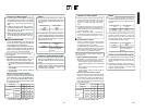
AUDIO OUTPUT switches and output
channels
In the following cases, the channels that receive
output from the AUDIO OUTPUT terminal vary
according to the setting of the AUDIO OUTPUT
switch. The table below shows the channels.
• During playback of tapes recorded in the 32kHz
audio mode.
• During audio dubbing.
• In the EE mode of DV input in the 32kHz audio
mode.
• In the 48kHz audio mode or during normal re-
cording, output goes to CH1 and CH2 regard-
less of the setting of the switch.
• When audio dubbing is paused, output goes to
CH3 and CH4.
Analog audio (2 channels)